Nuclear medical diagnosis apparatus

Inactive Publication Date: 2009-04-09
HITACHI LTD
View PDF5 Cites 0 Cited by
  • Summary
  • Abstract
  • Description
  • Claims
  • Application Information

AI Technical Summary

Benefits of technology

[0013]The present invention has been invented to solve the above described problems and provides a nuclear medical diagnosis apparatus capable of automatically performing a correction process, and speedily and stably switching between this correction process and an imaging process without increasing the size of the apparatus.
[0015]Such a configuration of the present invention makes it possible to revolve the correction radiation source around the body axis of the examinee, irradiate correction radiation and execute a correction process. When this correction process ends, the correction radiation source is accommodated in the radiation source chamber provided in the revolving mechanism and the process can immediately move to an imaging process. Moreover, since this radiation source chamber is provided in the revolving mechanism, it never occupies a separate space. Furthermore, since the orbit of the revolving correction radiation mechanism can be set close to the radiation detector, it is possible to shorten the inner diameter of the measuring space in which the examinee is inserted.
[0016]The present invention provides the following effects. That is, the present invention provides a nuclear medical diagnosis apparatus capable of performing a correction process and switching from a correction process to an imaging process speedily and stably in a simplified configuration without increasing the size of the apparatus and obtaining the examinee's tomographic image of high quality.

Problems solved by technology

However, radiation emitted from the emitter (positron emitter or single photon emitter) taken into the examinee's body in such a nuclear medical diagnosis apparatus is absorbed or scattered and attenuates in the process of traveling in the examinee's body.
Such attenuation of radiation deteriorates the image quality of the examinee's tomographic image obtained.

Method used


Image

  • Nuclear medical diagnosis apparatus
  • Nuclear medical diagnosis apparatus
  • Nuclear medical diagnosis apparatus

Examples


Embodiment Construction

[0018]Preferred embodiments of a PET apparatus as a nuclear medical diagnosis apparatus of the present invention will be explained in detail with reference to the attached drawings as appropriate.

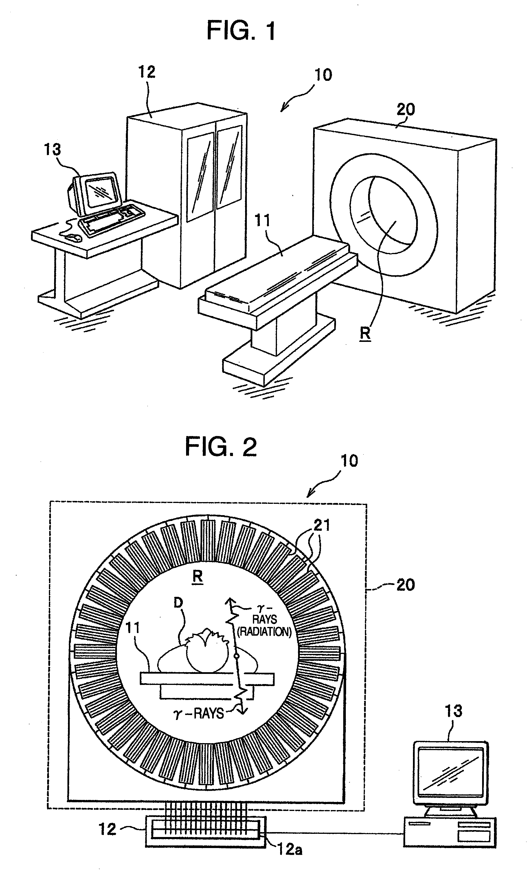
[0019]As shown in FIG. 1, the PET apparatus 10 of this embodiment is constructed of a bed 11, a data processing apparatus 12, a display apparatus 13 and an imaging apparatus 20.

[0020]The PET apparatus 10 configured in this way is designed to insert an examinee placed on the bed 11 into a measuring space R, detect γ-rays (radiation) emitted from tumor tissue using the imaging apparatus 20, carry out data processing on this detected signal using the data processing apparatus 12, identify points on the coordinate space generated by radiation, image this aggregate of points and display the image as tomography using the display apparatus 13. In this way, the PET apparatus 10 identifies the tumor region in the examinee's body.

[0021]On the other hand, when carrying out a medical diagnosis using th...


PUM


Abstract

A nuclear medical diagnosis apparatus comprises a nuclear radiation detector for detecting a nuclear radiation generated by a nuclide arranged in a body of a subject, a correcting radiation applying mechanism for directing a correcting radiation generated by a correcting radiation source to the subject so that the correcting radiation passes through the subject to be detected by the nuclear radiation detector, andan orbital mechanism arranged to rotate the correcting radiation applying mechanism to orbit around an body axis of the subject, and having a radiation source container by which the correcting radiation source is contained.

Description

TECHNICAL FIELD[0001]The present invention relates to a nuclear medical diagnosis apparatus using radiation, and more particularly, to a nuclear medical diagnosis apparatus provided with a correction radiation source for carrying out medical diagnosis with a high degree of accuracy.BACKGROUND ART[0002]Among nuclear medical diagnosis apparatuses that carry out medical diagnosis using radiation, a positron emission computed tomography apparatus (hereinafter referred to as “PET”) or a single photon emission computed tomography apparatus (hereinafter referred to as “SPECT”) is a technique of obtaining tomography by administering radiopharmaceutical to an examinee (patient) and measuring a distribution of this administered radiopharmaceutical in the body. Adopting such a technique enables molecular level functions and detection of metabolism and makes it possible to provide tomography based on physical functions.[0003]As the radiopharmaceutical to be administered, the PET uses radiopharm...

Claims


Application Information

Patent Timeline
IPC IPC(8): G01T1/166G01T1/161
CPCG01T1/1648G01T1/1611
Inventor YANAGITA, NORIHITOOOIKE, MASAHITONAGAOKA, MASAMIKIMURA, SHIGERUKOZAWA, FUSAAKI
Owner HITACHI LTD
Why Eureka
Try Eureka