Electric Compressor

a compressor and electric technology, applied in the direction of positive displacement liquid engines, piston pumps, liquid fuel engines, etc., can solve the problem of insufficient insulation inside the sealed container,

Active Publication Date: 2014-12-25
SANDEN CORP
View PDF4 Cites 18 Cited by
  • Summary
  • Abstract
  • Description
  • Claims
  • Application Information

AI Technical Summary

Problems solved by technology

However, such through holes connecting the sealed container and the airtight terminal section in the compressor might allow the liquid refriger

Method used


Image

  • Electric Compressor
  • Electric Compressor
  • Electric Compressor

Examples


Embodiment Construction

[0021]Hereinafter, desirable examples of the present invention will be explained with reference to figures.

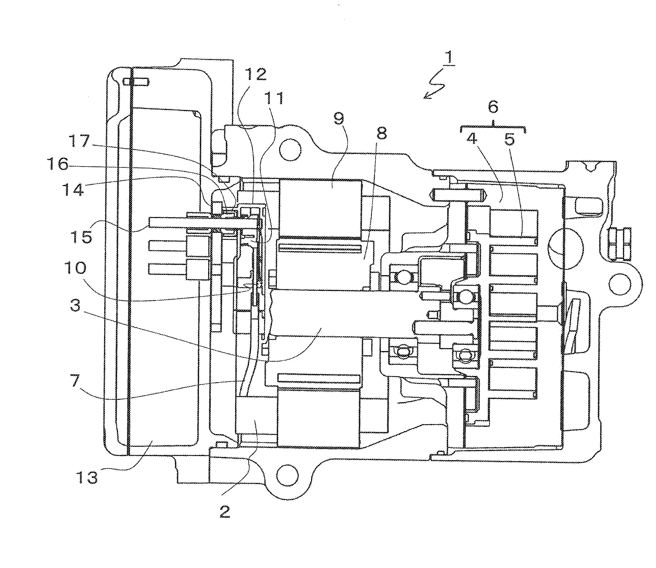
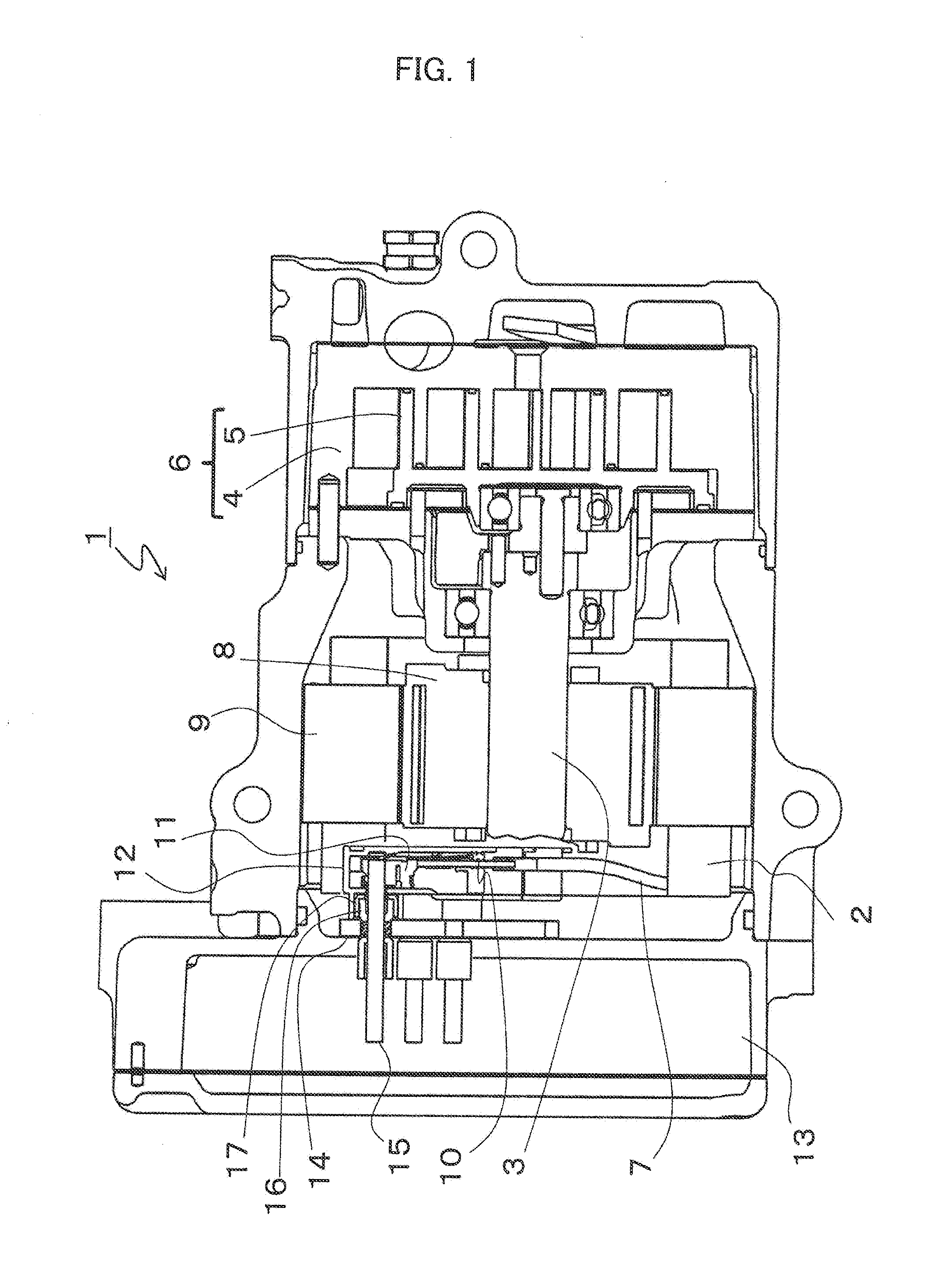
[0022]FIG. 1 is a longitudinal section view showing electric compressor 1 according to the present invention, Main shaft 3 driven to rotate by motor 2 makes movable scroll 4 swing so that refrigerant is compressed in compression mechanism 6 consisting of movable scroll 4 and fixed scroll 5. Electric current input to motor 2 through motor conducting wire 7 generates magnetic field to rotate rotor 8 driving main shaft 3 to rotate around stator 9.

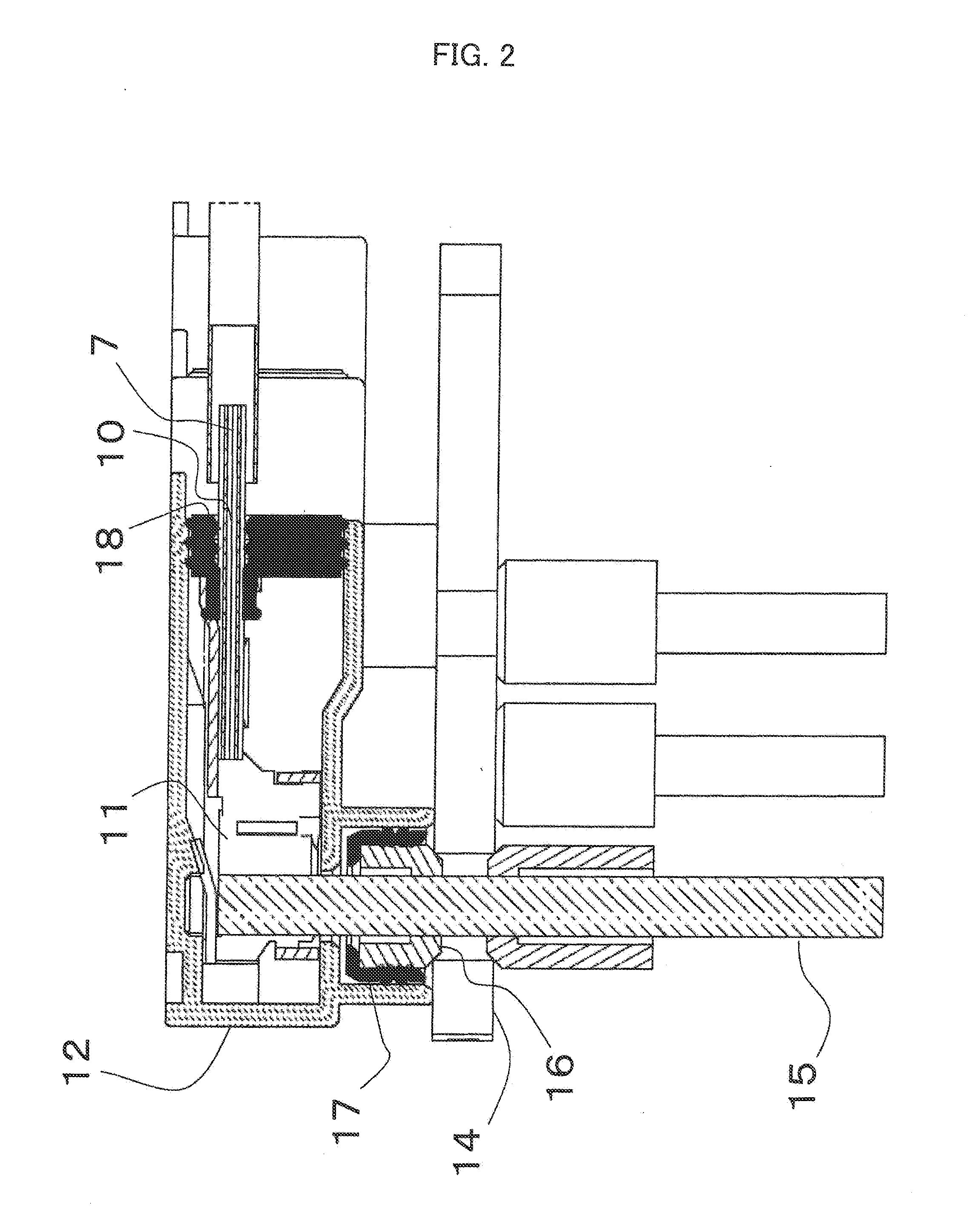
[0023]Motor conducting wire 7, which has been made by coating several bared motor windings as leaving the tip uncoated, is connected to connector terminal 11 via vacuum flow path 10 formed with gaps of conducting wire at the exposed tip. Refrigerant and lubricating oil flowing inside electric compressor 1 can flow via vacuum flow path 10 into connector housing 12 which houses connector terminal 11.

[0024]Connector terminal 11 connects to l...


PUM


Abstract

An electric compressor which compresses a coolant by driving a compression mechanism with a motor which is drive controlled by a drive circuit, said compressor being characterized by having a lead pin connected to a current output section of the drive circuit, and a connector which, by being mounted on the lead pin, can provide electrical continuity between the current output section of the drive circuit and a current input section of the motor, said connector being provided with a connector terminal which contacts the lead pin at the time of mounting on the lead pin, a connector housing which houses the connector terminal, a vacuum flow path that communicates the inside of the connector housing with the outside thereof, and a sealing member which provides a seal between the connector housing and the vacuum flow path. Thus, provided is a compressor which is easy to produce and for which it is possible to secure the electrical insulation properties of the interior of the compressor while homogenizing the internal pressure thereof.

Description

TECHNICAL FIELD OF THE INVENTION[0001]The present invention relates to an electric compressor having a motor controlled with a drive circuit such as inverter.BACKGROUND ART OF THE INVENTION[0002]An electric compressor mounted on vehicles or the like is provided with an airtight terminal section having connector terminals at which an electric current output from an inverter is input through lead pins (current-carrying part) of a hermetic plate to a motor winding. In such a case, the connector terminals are generally fixed to the hermetic plate with a cluster housing which houses a plurality of connector terminals.[0003]The airtight terminal section is designed to be inside a compressor housing (sealed container) to form a compact electric compressor. When refrigerant as a fluid to be compressed is flowing in the compressor housing, a pressure difference might he generated between the inside and outside of the airtight terminal if the airtight terminal section is completely sealed and...

Claims


Application Information

Patent Timeline
IPC IPC(8): H02K3/44H02K11/00H02K5/12
CPCH02K3/44H02K11/0094H02K5/12F04B35/04F04C18/0215F04C2240/803F04C2240/808F04B39/00
Inventor TAGUCHI, MASANORIHASEGAWA, TAKEHIROKOYAMA, SHIGEYUKI
Owner SANDEN CORP
Why Eureka
Try Eureka