Lithographic hotspot detection using multiple machine learning kernels

a machine learning and hotspot detection technology, applied in the field of hotspot identification, can solve the problems of long runtime, many regions of layouts may still be susceptible to lithography process, unwanted shape distortion of printed layout patterns,

Inactive Publication Date: 2014-12-04
SYNOPSYS INC
View PDF17 Cites 29 Cited by
  • Summary
  • Abstract
  • Description
  • Claims
  • Application Information

AI Technical Summary

Benefits of technology

The patent describes a computer-implemented method and computer-readable storage medium for identifying hotspots on an integrated circuit layout. The method involves training different machine learning kernels to identify different types of hotspot topologies. The method involves applying layout clips that may contain hotspots to the machine learning kernels and combining the results to identify hotspots within the clips. The system can also classify hotspots and non-hotspots based on their topologies and extract critical features from them to create kernels that can identify specific hotspot topologies. The technical effect of this patent is to provide a more accurate and efficient method for identifying hotspots on integrated circuit layouts, which can help improve the manufacturing process and reliability of the final product.

Problems solved by technology

In advanced process technology, the ever-growing subwavelength lithography gap causes unwanted shape distortions of the printed layout patterns.
Although design rule checking (DRC) and reticle / resolution enhancement techniques (RET), such as optical proximity correction (OPC) and subresolution assist features (SRAF), can alleviate the printability problem, many regions on a layout may still be susceptible to lithography process.
However, the simulation suffers from an extremely high computational complexity and long runtime.
Pattern matching is the fastest hotspot detection approach and is good at detecting pre-characterized hotspot patterns, but has a limited flexibility to recognize previously unseen ones.

Method used


Image

  • Lithographic hotspot detection using multiple machine learning kernels
  • Lithographic hotspot detection using multiple machine learning kernels
  • Lithographic hotspot detection using multiple machine learning kernels

Examples


Embodiment Construction

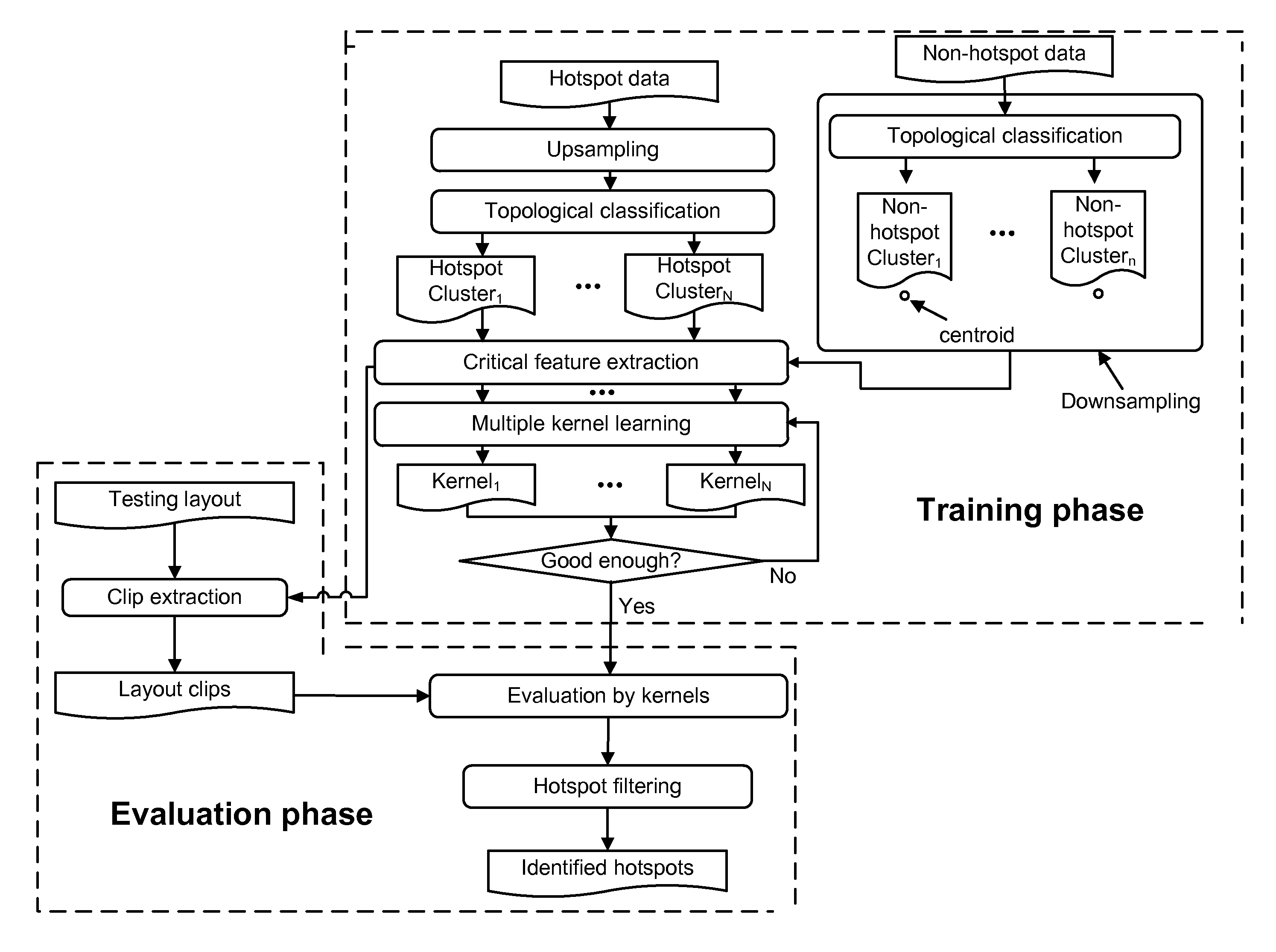
[0027]The Figures (FIGS.) and the following description describe certain embodiments by way of illustration only. One skilled in the art will readily recognize from the following description that alternative embodiments of the structures and methods illustrated herein may be employed without departing from the principles described herein. Reference will now be made in detail to several embodiments, examples of which are illustrated in the accompanying figures. It is noted that wherever practicable similar or like reference numbers may be used in the figures and may indicate similar or like functionality.

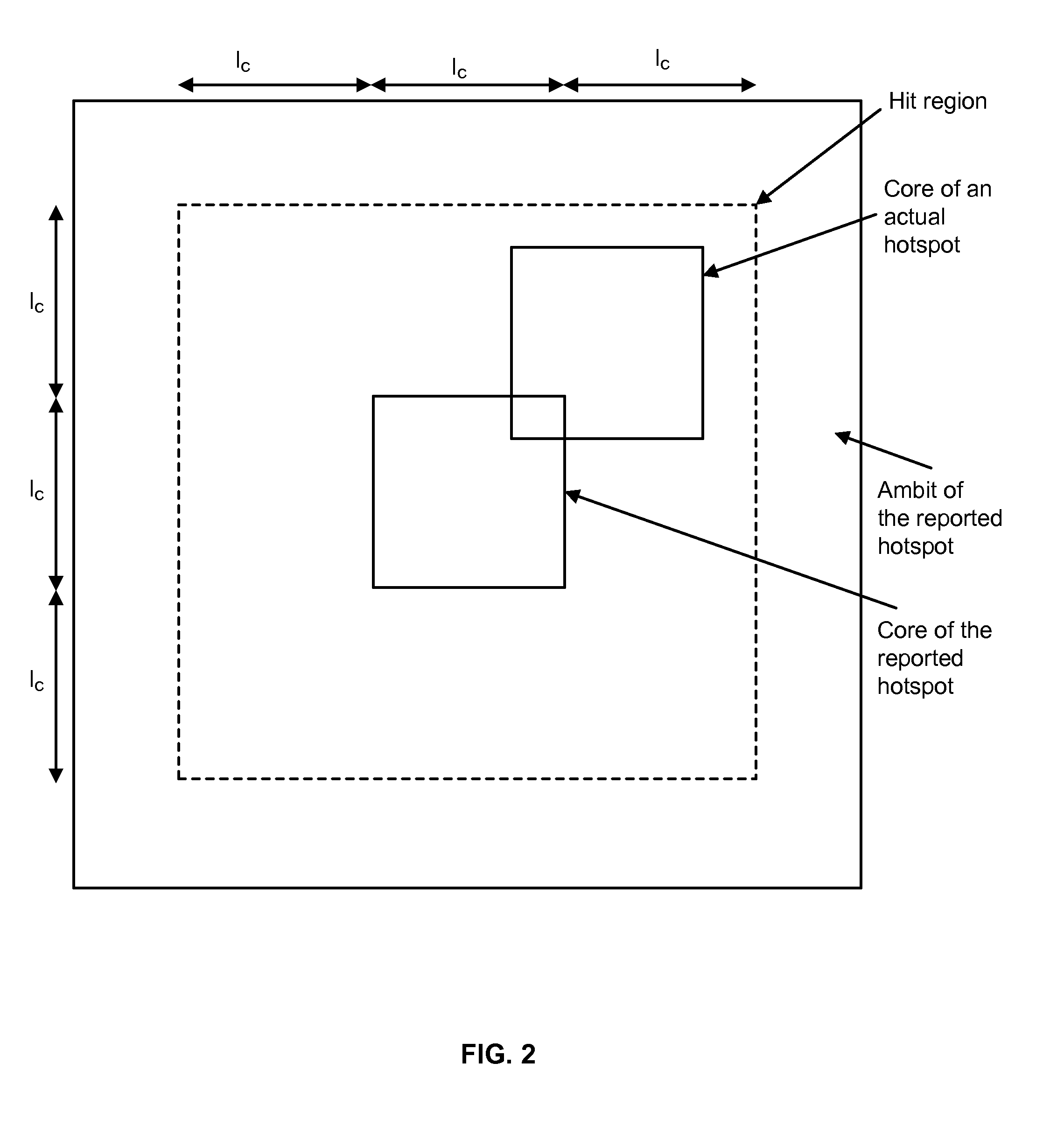
[0028]As used herein, a “hotspot” is a layout pattern that is at risk of inducing a printability issue at the fabrication stage. As used herein, a “hit” is an actual hotspot that has been correctly identified as a hotspot. Accuracy is the ratio of the number of total hits over the number of all actual hotspots. Additionally, as used herein, an “extra” is a non-hotspot that is mistake...


PUM


Abstract

A hotspot detection system that classifies a set of hotspot training data into a plurality of hotspot clusters according to their topologies, where the hotspot clusters are associated with different hotspot topologies, and classifies a set of non-hotspot training data into a plurality of non-hotspot clusters according to their topologies, where the non-hotspot clusters are associated with different topologies. The system extracts topological and non-topological critical features from the hotspot clusters and centroids of the non-hotspot clusters. The system also creates a plurality of kernels configured to identify hotspots, where each kernel is constructed using the extracted critical features of the non-hotspot clusters and the extracted critical features from one of the hotspot clusters, and each kernel is configured to identify hotspot topologies different from hotspot topologies that the other kernels are configured to identify.

Description

CROSS REFERENCE TO RELATED APPLICATION[0001]This application claims priority to Provisional Patent Application No. 61 / 828,915, filed May 30, 2013, which is incorporated herein by reference.BACKGROUND[0002]1. Field of Disclosure[0003]This disclosure relates to the field of hotspot identification generally, and specifically to improved hotspot identification using machine learning.[0004]2. Description of the Related Art[0005]In advanced process technology, the ever-growing subwavelength lithography gap causes unwanted shape distortions of the printed layout patterns. Although design rule checking (DRC) and reticle / resolution enhancement techniques (RET), such as optical proximity correction (OPC) and subresolution assist features (SRAF), can alleviate the printability problem, many regions on a layout may still be susceptible to lithography process. These regions, so-called lithography hotspots, should be detected and corrected before mask synthesis. Hotspot detection, therefore, is a...

Claims


Application Information

Patent Timeline
IPC IPC(8): G06N99/00G06N20/10
CPCG06N99/005G06T7/001G06T2207/30144G06N20/00G06N20/10G03F7/705G03F7/70433G06F18/2411
Inventor CHIANG, CHARLES C.YU, YEN-TINGLIN, GENG-HEJIANG, HUI-RU
Owner SYNOPSYS INC
Why Eureka
Try Eureka