Discharge lamp

a discharge lamp and discharge tube technology, applied in the direction of discharge tube main electrodes, incadescent cooling arrangements, lighting and heating apparatus, etc., can solve the problems of short service life, high efficiency, and short discharge lamp life, so as to reduce the length and volume of the entire discharge lamp, prevent heat emission, and minimize the amount of heat emitted

Inactive Publication Date: 2014-11-27
KANG SEONG JIN +1
View PDF1 Cites 0 Cited by
  • Summary
  • Abstract
  • Description
  • Claims
  • Application Information

AI Technical Summary

Benefits of technology

The present invention aims to solve problems in the related art by proposing a discharge lamp that can minimize heat transfer and assembly time while maintaining excellent performance. The lamp uses a new design that eliminates the need for expensive amalgam and auxiliary amalgam, while still achieving high-temperature use.

Problems solved by technology

However, the bulb-type discharge lamp is configured such that its length is very long compared to an incandescent lamp.
Therefore, its use is limited although it has a relatively longer lifetime and higher efficiency compared to those of the incandescent lamp.
However, a problem with this compact discharge lamp is that heat generated by the discharge lamp is directly transferred to the stabilizer so that the temperature of the stabilizer rapidly increases to a very high temperature.
However, although the related art provides similar shapes in response to the above-mentioned demands for a variety of shapes, there are problems in that the overall volume increases, dull and stout configurations are provided, and light is not emitted toward the lower portion in which a stabilizer housing, if any, is provided.
In addition, when a cover is provided, the temperature of the discharge tube inside the cover may excessively increase.
This may also increase the temperature of the stabilizer, thereby reducing longevity.
However, the amalgam for high-temperature use has a problem in that it is not easy to light the lamp because of the low vapor pressure at room temperature.
Accordingly, in order to solve this problem, auxiliary amalgam, which is produced by applying a thin layer of indium on a molybdenum matrix having the form of a thin sheet or net, must be used, thereby increasing the cost of manufacture.

Method used


Image

  • Discharge lamp
  • Discharge lamp
  • Discharge lamp

Examples


Embodiment Construction

[0032]Reference will now be made in greater detail to preferred embodiments of the invention, examples of which are illustrated in the accompanying drawings. Wherever possible, the same reference numerals will be used throughout the drawings and the description to refer to the same or like parts.

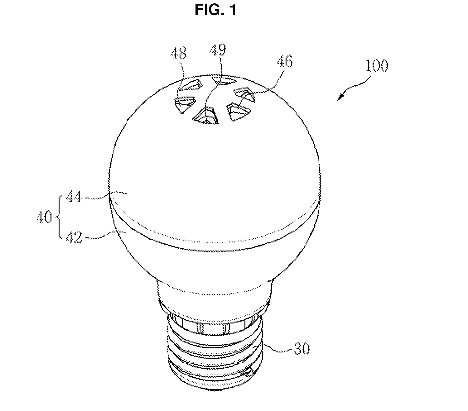
[0033]FIG. 1 is a perspective view showing a discharge lamp 100 according to an exemplary embodiment of the invention.

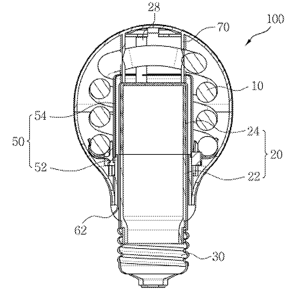
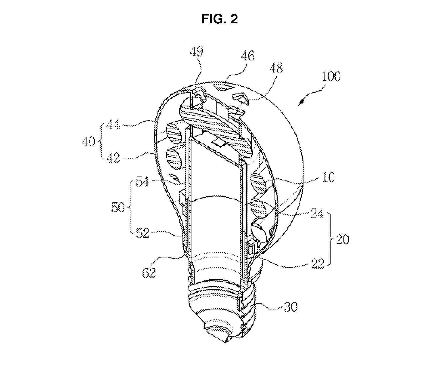
[0034]Referring to FIG. 1, a discharge lamp 100 may include a discharge tube 10, which emits light. In this embodiment, the discharge tube 10 extends a predetermined length, and is bent a predetermined number of times, such that a containing space is defined therein. Although FIG. 1 shows a spirally bent discharge tube 10, this is not intended to be limiting. Any shape that can define the inner space therein is available.

[0035]A stabilizer housing 20 (refer to FIG. 2) may be provided inside the space, which is defined inside the discharge tube 10. The stabilizer housing 20, w...


PUM


Abstract

A discharge lamp includes a discharge tube, a stabilizer housing provided in the inner space that is defined by the discharge tube, the stabilizer housing containing a stabilizer therein, a cover surrounding the discharge tube; a base connected to the stabilizer housing, and a heat insulating means. The heat insulating means prevents the heat of the discharge tube from being transferred to the stabilizer.

Description

REFERENCE TO RELATED APPLICATIONS[0001]This is a continuation of pending International Patent Application PCT / KR2013 / 001065 filed on Feb. 12, 2013, which designates the United States and claims priority of Korean Patent Application No. 10-2012-0013783 filed on Feb. 10, 2012, the entire contents of which are incorporated herein by reference.FIELD OF THE INVENTION[0002]The present invention relates to a discharge lamp.BACKGROUND OF THE INVENTION[0003]Generally, discharge lamps are widely used in a variety of illuminating facilities. The configuration of a discharge lamp includes a transparent discharge tube, which is made of a transparent material such as glass or quartz, and a stabilizer, which supplies power in order to drive the discharge tube. In the meantime, a discharge gas, such as mercury steam and buffer gas, is contained inside discharge tubes in order to generate electric discharge.[0004]Discharge lamps operate as follows. When power is supplied to the discharge tube throug...

Claims


Application Information

Patent Timeline
Patent Type & Authority Applications(United States)
IPC IPC(8): H01J61/52H01J61/34F21V29/15
CPCH01J61/34H01J61/523H01J61/327H01J61/56F21V17/00F21V29/15
Inventor KANG, SEONG JINKANG, SEONG SEOK
Owner KANG SEONG JIN
Why Eureka
Try Eureka