Variable beam control antenna for mobile communication system

a mobile communication system and beam control technology, applied in the direction of individual energised antenna arrays, resonant antennas, antenna earthings, etc., can solve the problems of unstable antenna characteristics and high-cost mechanical equipment, and achieve excellent stability during antenna installation, reduce the possibility of malfunction, and improve the stability of antenna characteristics

Active Publication Date: 2014-11-13
KMW INC
View PDF7 Cites 8 Cited by
  • Summary
  • Abstract
  • Description
  • Claims
  • Application Information

AI Technical Summary

Benefits of technology

The present invention provides a variable beam control antenna for a mobile communication system that has excellent stability during installation, is less likely to malfunction due to external factors, and has more stable antenna characteristics. Its simpler structure enables vertical beam tilt adjustment, horizontal steering adjustment, and horizontal beam width control. This makes it suitable for high functionality, low cost production, and network optimization.

Problems solved by technology

As such, antennas for mobile communication systems have a request for a structure enabling vertical beam tilt adjustment, horizontal steering adjustment, and horizontal beam width control, as well as an increasing demand for formation of more optimized beam patterns for respective sectors, but application of such a structure requires that comparatively complicated, high-cost mechanical equipment be additionally employed, which could possibly make antenna characteristics unstable.

Method used


Image

  • Variable beam control antenna for mobile communication system
  • Variable beam control antenna for mobile communication system
  • Variable beam control antenna for mobile communication system

Examples


Embodiment Construction

[0021]Hereinafter, an exemplary embodiment of the present invention will be described in detail with reference to the accompanying drawings. In the drawings, the same components are given the same reference numerals.

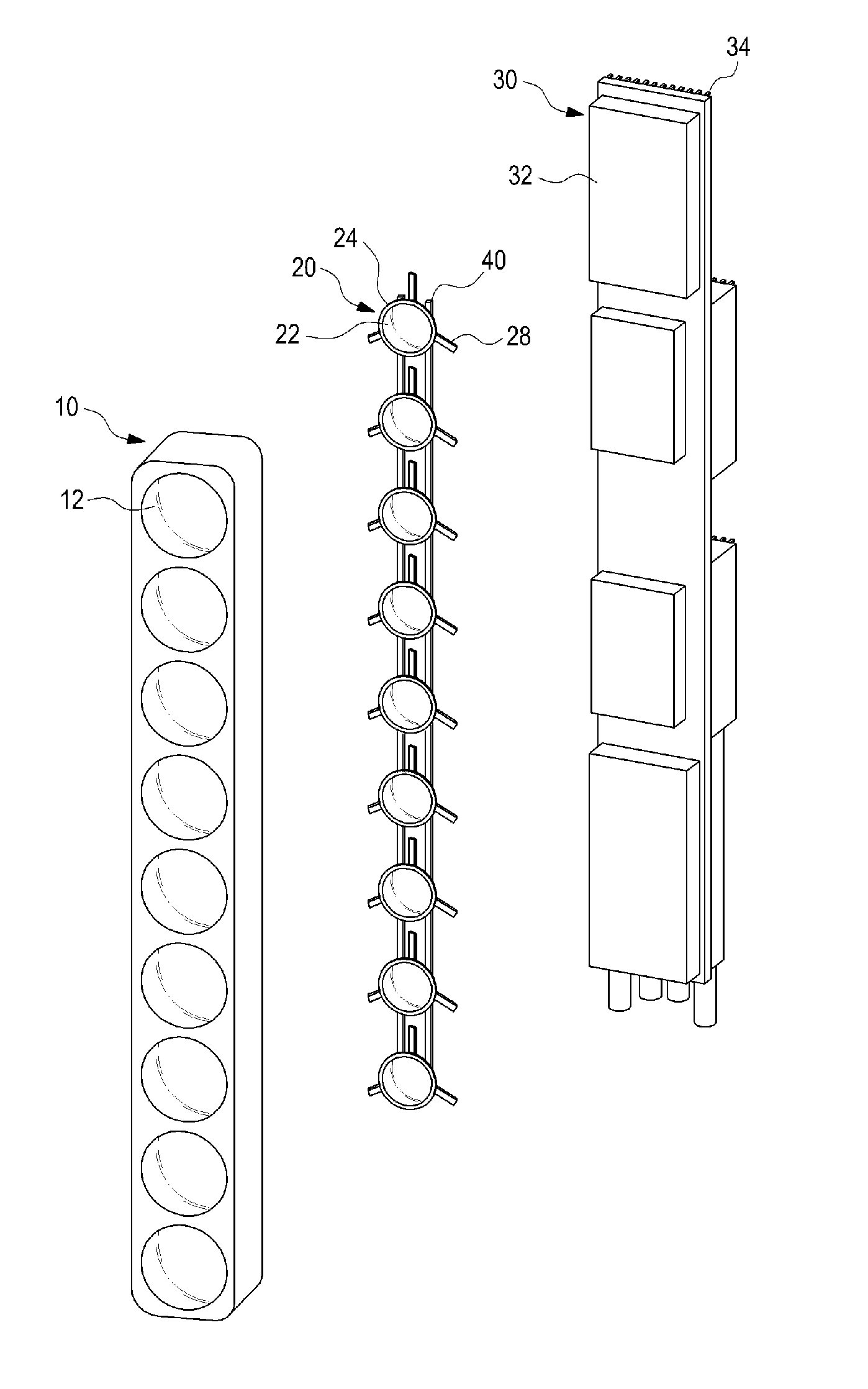
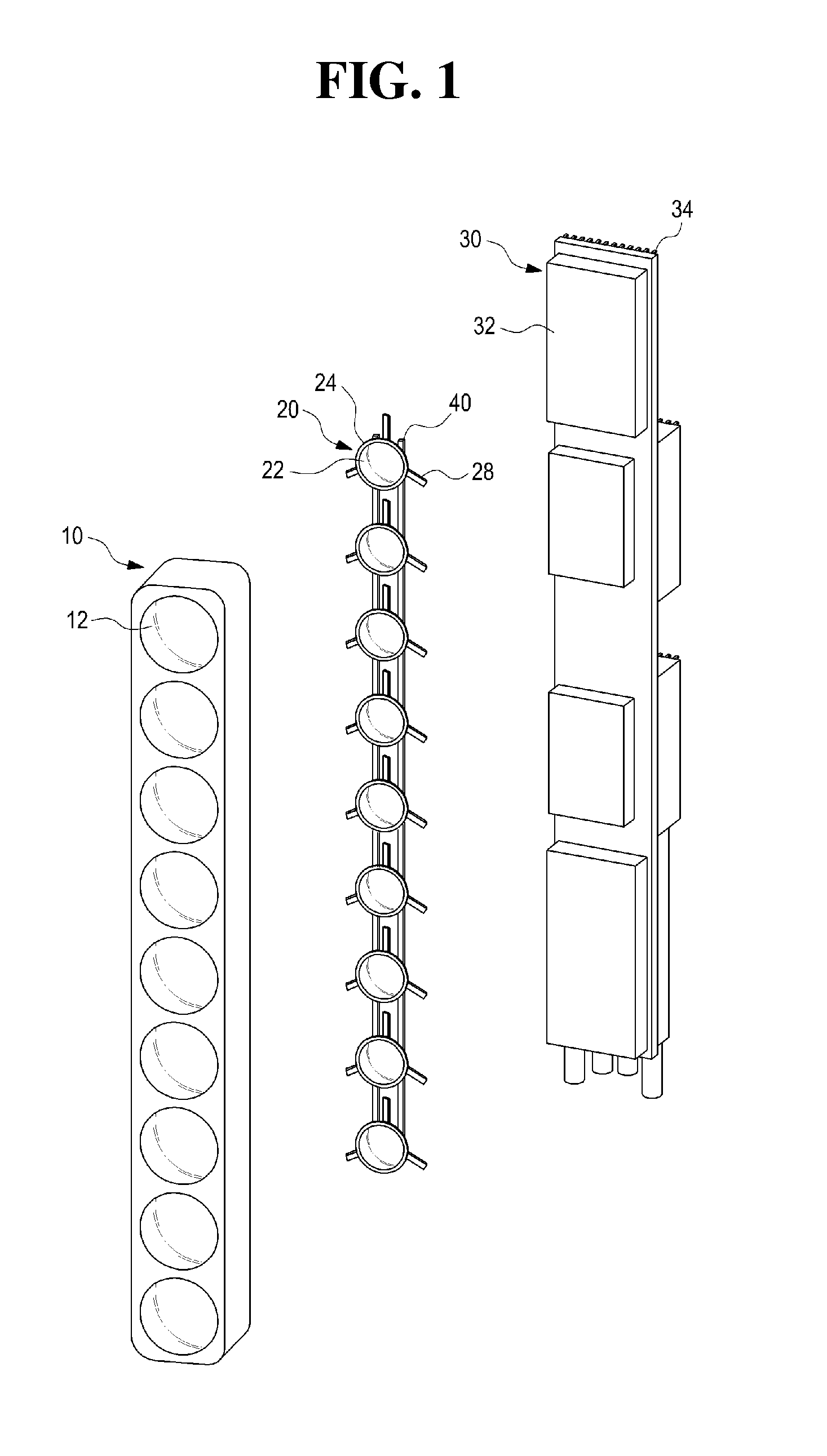
[0022]FIG. 1 is a schematic exploded perspective view illustrating a structure of a variable beam control antenna for a mobile communication system according to an embodiment of the present invention. Referring to FIG. 1, the antenna according to an embodiment of the present invention includes a radome 10 formed on a front surface from which signals are radiated; a number of radiation units 20 arranged vertically; a frame unit 30 supporting the radome 10 and the radiation units 20; and a direction variable module (including a rack gear unit 40, an up / down variable unit 50, and a left / right variable unit 60 described later) configured to rotate each of the radiation units 20 upwards / downwards and leftwards / rightwards with respect to one reference point in response to an e...


PUM


Abstract

The present invention relates to a variable beam control antenna for a mobile communication system, the antenna comprising: a radome formed on the front surface at which a signal is emitted; multiple emitters vertically arranged in at least one row; a frame portion for supporting the radome and the multiple emitters; and a direction-changing module which rotates each of the multiple emitters vertically and horizontally with respect to a reference point in order to change the emission direction of the multiple emitters.

Description

CROSS-REFERENCE TO RELATED APPLICATIONS[0001]This application is a continuation application of International Application No. PCT / KR2013 / 002917 filed on Apr. 8, 2013, which claims priority to Korean Application No. 10-2012-0038113 filed on Apr. 12, 2012, which applications are incorporated herein by reference.TECHNICAL FIELD[0002]The present invention relates to an antenna applied to a base station or a repeater in a mobile communication system, and more particularly, to a variable beam control antenna designed to enable the antenna's vertical beam tilt adjustment, horizontal steering adjustment, horizontal beam width control, etc.BACKGROUND ART[0003]Vertical beam tilt control antennas, which are capable of vertical (and / or horizontal) beam tilting, have recently been widely used as base station antennas in mobile communication systems due to many advantages.[0004]Beam tilt schemes of vertical beam tilt control antennas can be largely divided into a mechanical beam tilt scheme and an...

Claims


Application Information

Patent Timeline
IPC IPC(8): H01Q3/08H01Q3/18
CPCH01Q3/08H01Q3/18H01Q1/1264H01Q1/246H01Q1/42H01Q1/48H01Q9/28H01Q19/13H01Q21/062H01Q21/08H01Q3/32
Inventor MOON, YOUNG-CHANSO, SUNG-HWANKIM, IN-HOCHOI, OH-SEOGYANG, HYOUNG-SEOK
Owner KMW INC
Why Eureka
Try Eureka