
Architecture of Spare Wiring Structures for Improved Engineering Change Orders

a technology of engineering change order and wiring structure, which is applied in the direction of electrical equipment, solid-state devices, special data processing applications, etc., can solve the problems of schedule delays, increased manufacturing costs, and significant cost of the production of each photomask and the set as a whole, so as to reduce the complexity of an engineering change order

Inactive Publication Date: 2014-11-13
BLACKCOMB DESIGN AUTOMATION
View PDF7 Cites 21 Cited by
  • Summary
  • Abstract
  • Description
  • Claims
  • Application Information

AI Technical Summary

Benefits of technology

This patent describes a method for designing an integrated circuit that makes it easier to modify the circuit's layout. The design includes multiple layers of electrically conductive material, and each layer has specific locations where access points can be added or new connections can be made. This patterned placement reduces the complexity of making changes to the circuit's design. Additionally, the design includes spare parts that can be added at these locations, which further simplifies the circuit's modification. Overall, this method improves the flexibility and efficiency of integrated circuit design.

Problems solved by technology

The costs associated with the production of each photomask and the set as a whole is a significant part of the total cost of fabricating an integrated circuit.
If there are design errors or specification changes found after the photomask set has been manufactured, one or more of the photomasks must be redesigned and remanufactured.
If an engineering change requires the refabrication of too many photomasks, the increased manufacturing costs, schedule delays, and risks associated with the engineering change may warrant a full revision, in which case the entire photomask set must be redesigned and remanufactured.

Method used


Image

  • Architecture of Spare Wiring Structures for Improved Engineering Change Orders
  • Architecture of Spare Wiring Structures for Improved Engineering Change Orders
  • Architecture of Spare Wiring Structures for Improved Engineering Change Orders

Examples


Embodiment Construction

[0054]Reference will now be made in detail to embodiments, examples of which are illustrated in the accompanying drawings, wherein like reference numerals refer to the like elements throughout.

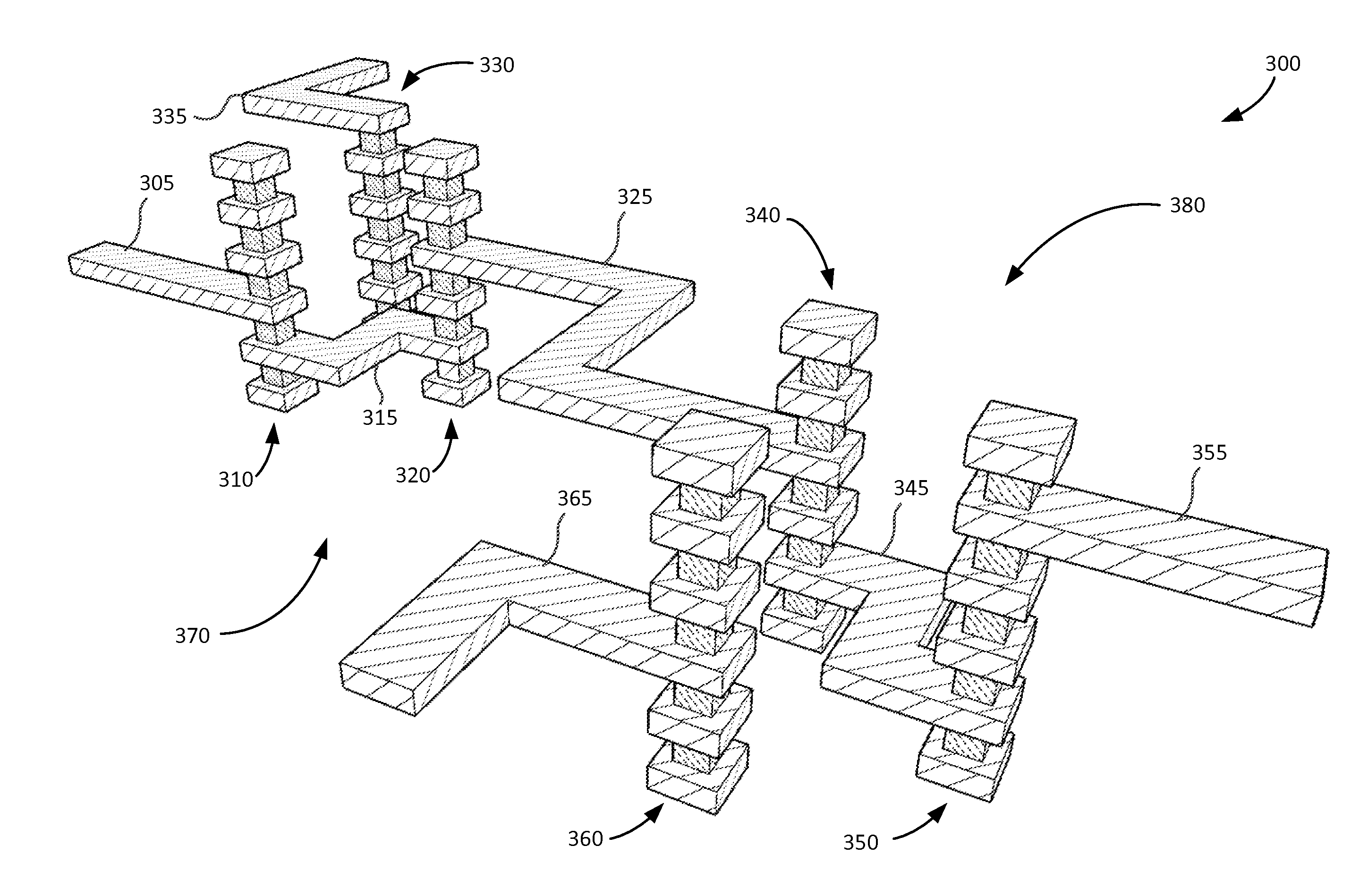
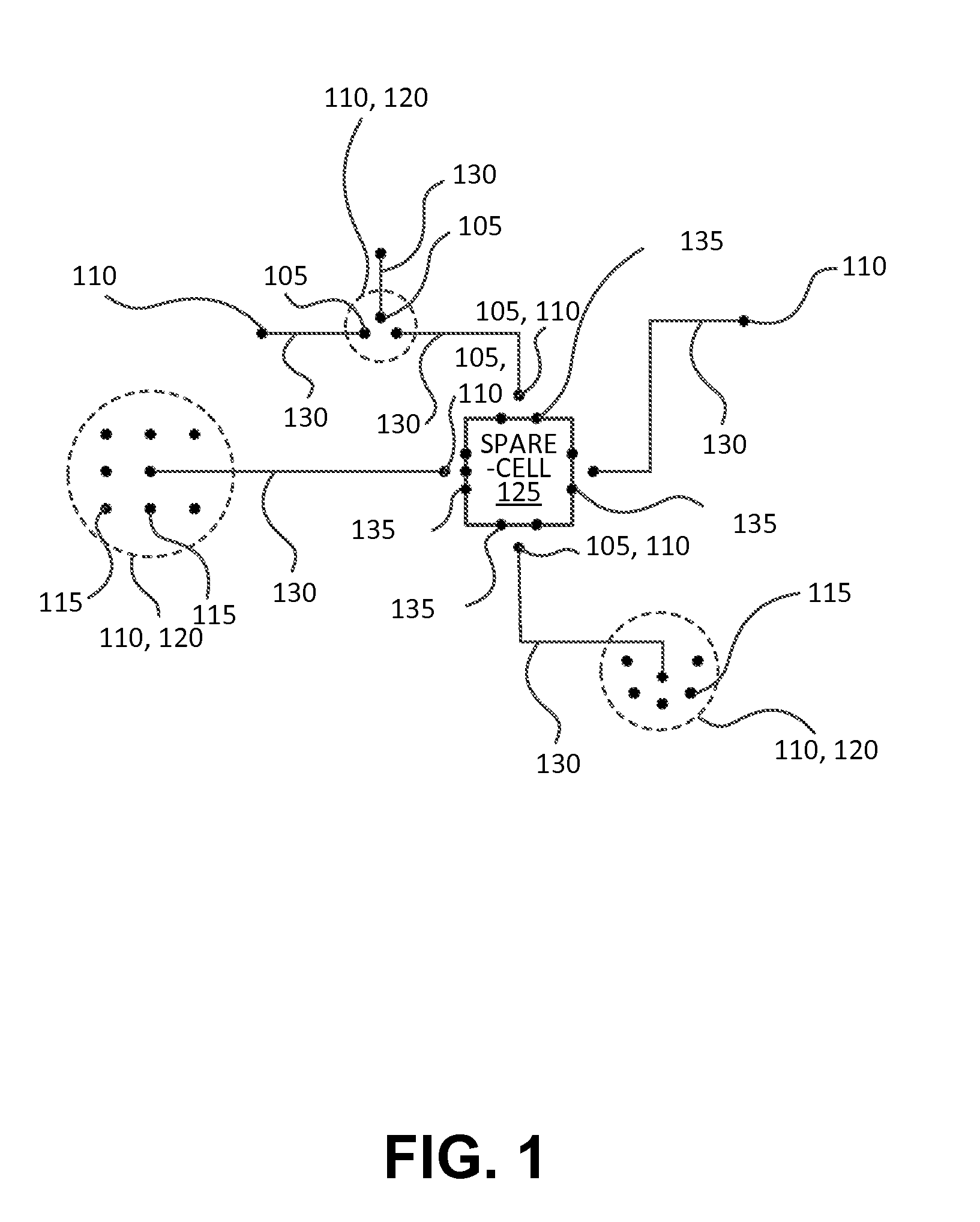
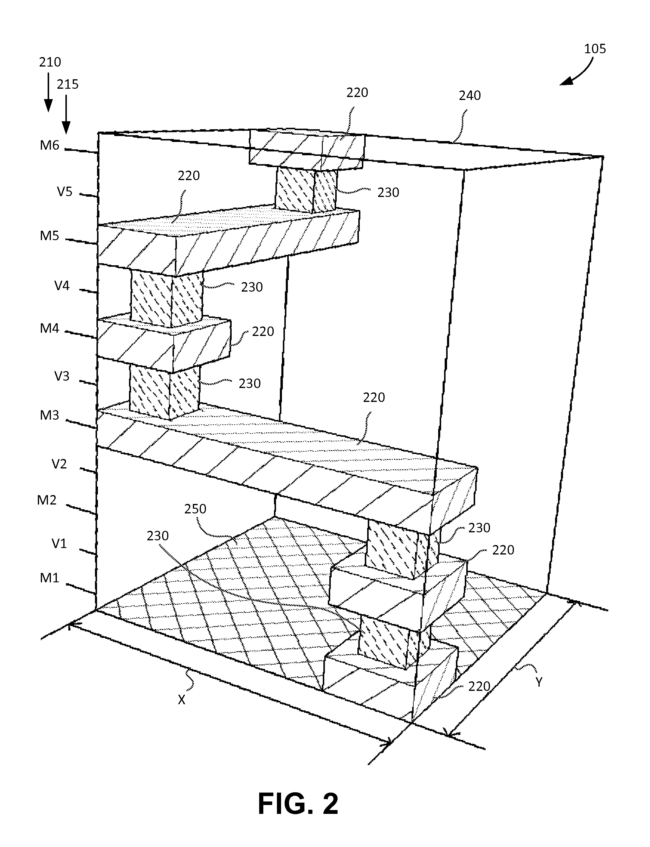
[0055]According to various embodiments, an architecture for integrated circuits includes spare wiring structures that are inserted into the physical design of an integrated circuit in order to facilitate or improve the process of modifying one or more of the operation, function, and performance characteristics of the integrated circuit, either pre- or post-fabrication. Modification of the design of the integrated circuit to change its operation, function, and / or performance characteristics is known as an engineering change order (ECO) process, in which engineering changes (ECs) are made to an integrated circuit design. The architecture of spare wiring structures increases the accessibility from circuit elements to spare-resources and to other circuit elements within the integrated circuit for ...


PUM


Abstract

An integrated circuit includes a substrate having a plurality of electronic devices, a plurality of interconnect layers disposed on one or both sides of the substrate, and a plurality of active electrically conductive interconnect layer structures. The plurality of interconnect layers include horizontal interconnect and vertical-interconnect-access (VIA) layers. The plurality of active electrically conductive interconnect layer structures are disposed on at least one of the plurality of interconnect layers and electrically coupled with at least one of the plurality of electronic devices. The integrated circuit also includes a plurality of spare electrically conductive interconnect layer structures disposed on at least one of the plurality of interconnect layers and electrically isolated from the plurality of active electrically conductive interconnect layer structures.

Description

RELATED APPLICATIONS[0001]This application claims the priority benefits of U.S. Provisional Patent Application No. 61 / 819,519, entitled “Architecture of Spare Wiring Structures for Improved Engineering Change Orders” and filed on May 3, 2013, in the U.S. Patent and Trademark Office, and U.S. Provisional Patent Application No. 61 / 830,556, entitled “Method and System for the Insertion of Spare Routing Resources for Engineering Change Orders in Integrated Circuits,” and filed on Jun. 3, 2013, the disclosures of both which are incorporated herein in their entirety by reference.BACKGROUND[0002]1. Field[0003]The field of the embodiments generally relates to improved techniques and architectures for modifying the physical design and realization of integrated circuits, and more specifically to an architecture of spare wiring structures for improved engineering change orders.[0004]2. Related Art[0005]Integrated circuit design typically involves a series of well-defined steps using a sequence...

Claims


Application Information

Patent Timeline
Patent Type & Authority Applications(United States)
IPC IPC(8): H01L23/48
CPCH01L23/481H01L23/525H01L23/528H01L2924/0002H01L23/522G06F30/39H01L2924/00
Inventor CICALO, JAMESHALLSCHMID, PETERMOLLAH, A.K.M. KAMRUZZAMAN
Owner BLACKCOMB DESIGN AUTOMATION
Learn More