Quick Drum Connect

a drum and connector technology, applied in the field of quick drum connections, can solve the problems of reducing the number of components reducing the time and expense required for a drum replacement operation, and reducing the difficulty of drum replacement and time-consuming operations

Inactive Publication Date: 2014-11-13
SCHLUMBERGER TECH CORP
View PDF21 Cites 9 Cited by
  • Summary
  • Abstract
  • Description
  • Claims
  • Application Information

AI Technical Summary

Benefits of technology

[0006]The disclosed embodiments may provide various technical advantages. For example, the disclosed winch assembly simplifies drum replacement procedures via reducing the number of components th

Problems solved by technology

These drum changes can be difficult and time-consuming operations with a number of steps required to disconnect the drum assembly from equipment adjacent the wellbore.
Lost rig time can therefore be considerable.
The changeover can

Method used


Image

  • Quick Drum Connect
  • Quick Drum Connect
  • Quick Drum Connect

Examples


Embodiment Construction

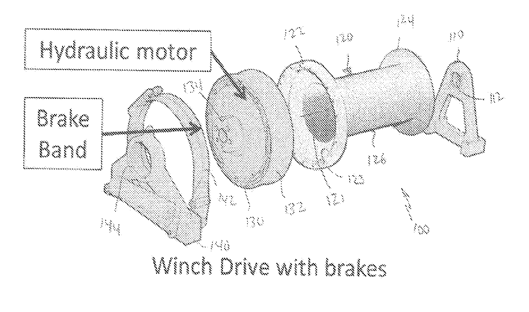
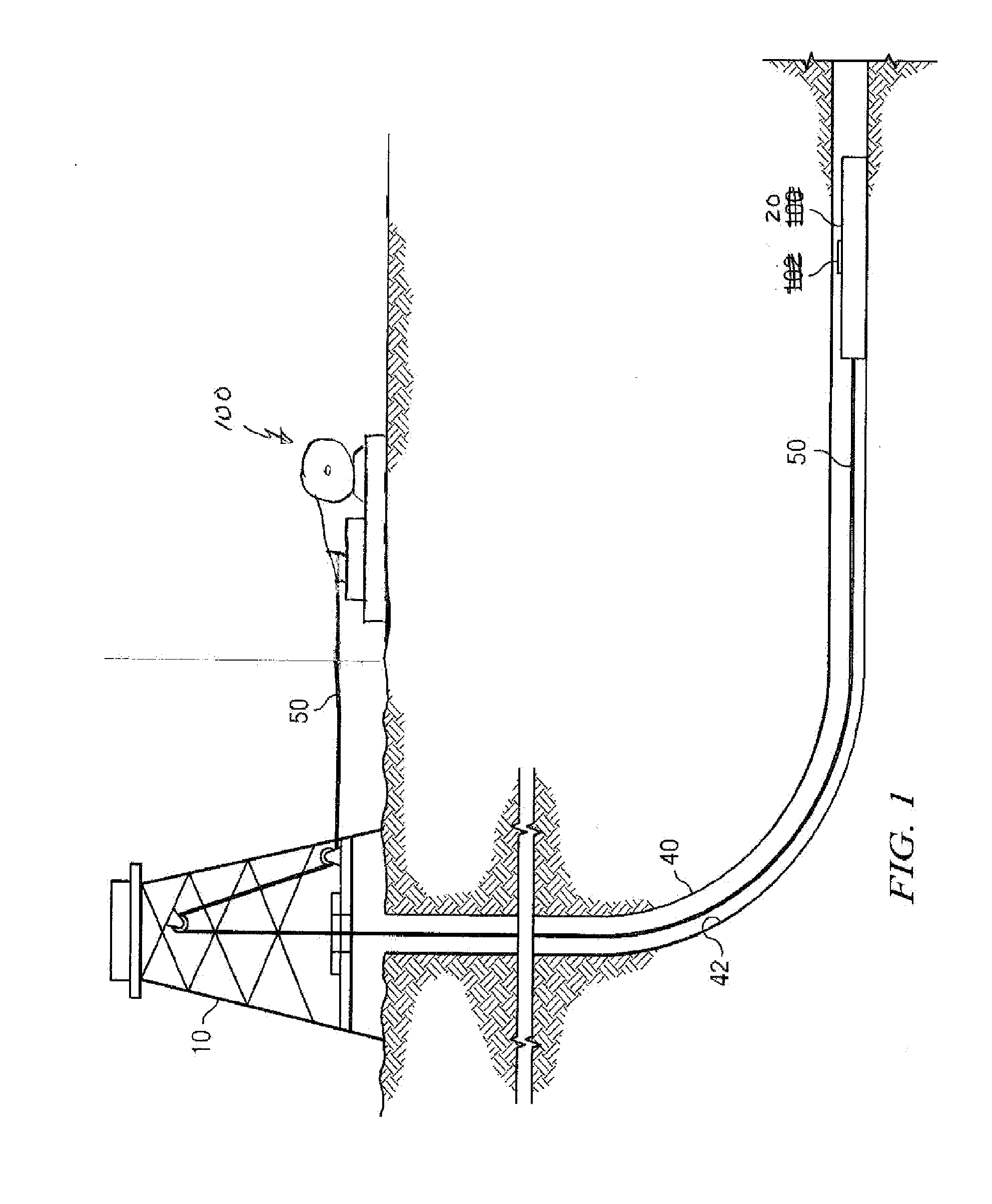
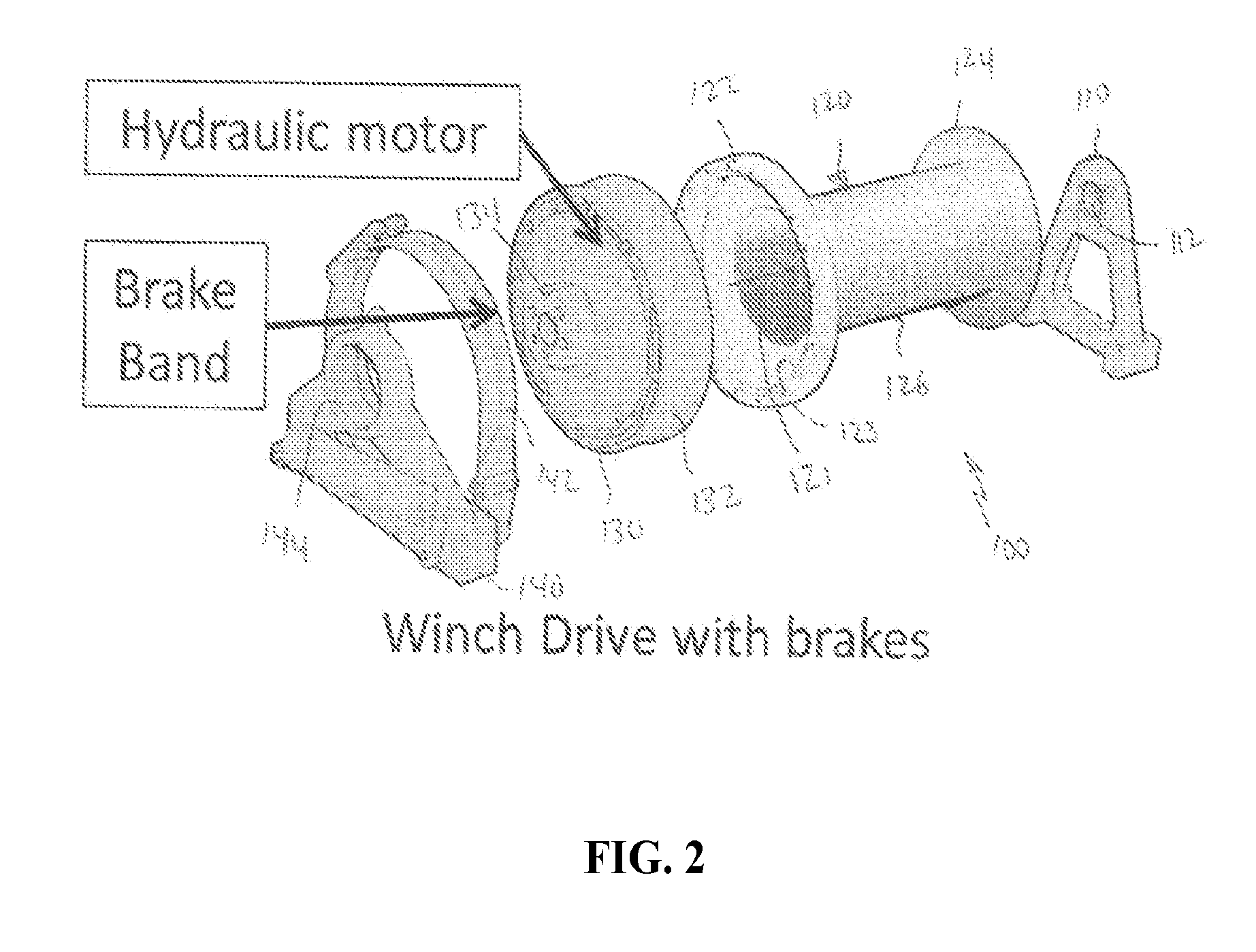
[0012]FIG. 1 depicts a drilling rig 10 suitable for employing certain downhole tool embodiments disclosed herein. In the depiction, a rig 10 is positioned over (or in the vicinity of) a subterranean oil or gas formation (not shown). The rig may include, for example, a derrick and a hoisting apparatus for lowering and raising various components into and out of the wellbore 40. A downhole tool 20 (e.g., a wireline or slick line tool) is deployed in the wellbore 40. The downhole tool may be connected to the surface, for example, via a wireline or slick line cable 50 which is in turn coupled to and at least partially coiled about the drum of a winch drive assembly 100.

[0013]During various wellbore operations downhole tool 20 may be lowered into the wellbore 40. In a highly deviated borehole, the tool 20 may alternatively or additionally be driven or drawn into the borehole using, for example, a downhole tractor or other conveyance means. The disclosed embodiments are not limited in this...


PUM


Abstract

A winch drive assembly includes a drum having a cylindrical spool located axially between a first hollow annular flange and a second substantially circular flange having a central axle. A hydraulic motor has an inner stator and an outer rotor, the outer rotor of which releasably engages the first hollow annular flange of the drum. A braking system is positioned adjacent the outer rotor of the hydraulic motor and a support member releasably engages the central axle of the second flange of the drum.

Description

FIELD OF THE INVENTION[0001]Disclosed embodiments relate generally to wellbore cabling systems and more particularly to a winch assembly having a removable drum for reeling wireline, slick line and / or coiled tubing.BACKGROUND INFORMATION[0002]Hydrocarbons, such as oil and natural gas, are obtained from subterranean formations by drilling wellbores that penetrate the hydrocarbon bearing formations. Such drilling operations commonly make use of cables and coiled tubing which are wound upon a drum (or spool) and installed near the wellbore.[0003]On occasion, the drum assembly may need to be changed for a different drum assembly (such as one with a longer or shorter cable or the like). In logging operations, it is not uncommon to change the drum from the logging unit a few times during the operation. These drum changes can be difficult and time-consuming operations with a number of steps required to disconnect the drum assembly from equipment adjacent the wellbore. Lost rig time can the...

Claims


Application Information

Patent Timeline
IPC IPC(8): E21B19/22E21B19/084B23P6/00B66D1/08
CPCE21B19/22B66D1/08E21B19/084B23P6/00B66D1/14Y10T29/4973
Inventor AUBRY, DOMINIQUE
Owner SCHLUMBERGER TECH CORP
Why Eureka
Try Eureka