
Optical temperature sensor and use of same

Active Publication Date: 2014-10-30
THE UNITED STATES OF AMERICA AS REPRESENTED BY THE SECRETARY OF THE COMMERCE +2
View PDF19 Cites 26 Cited by
  • Summary
  • Abstract
  • Description
  • Claims
  • Application Information

AI Technical Summary

Benefits of technology

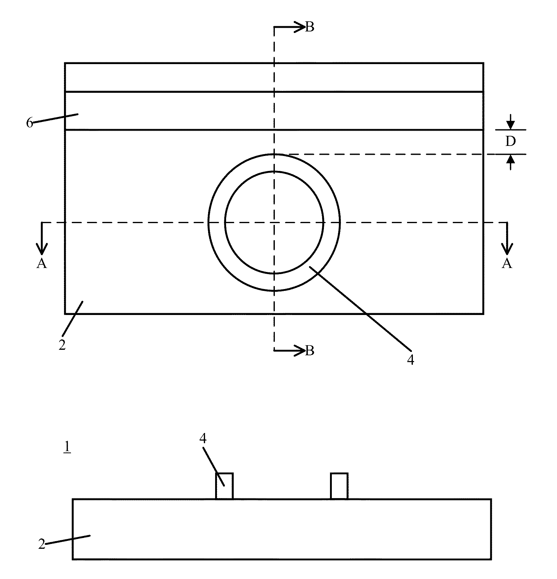
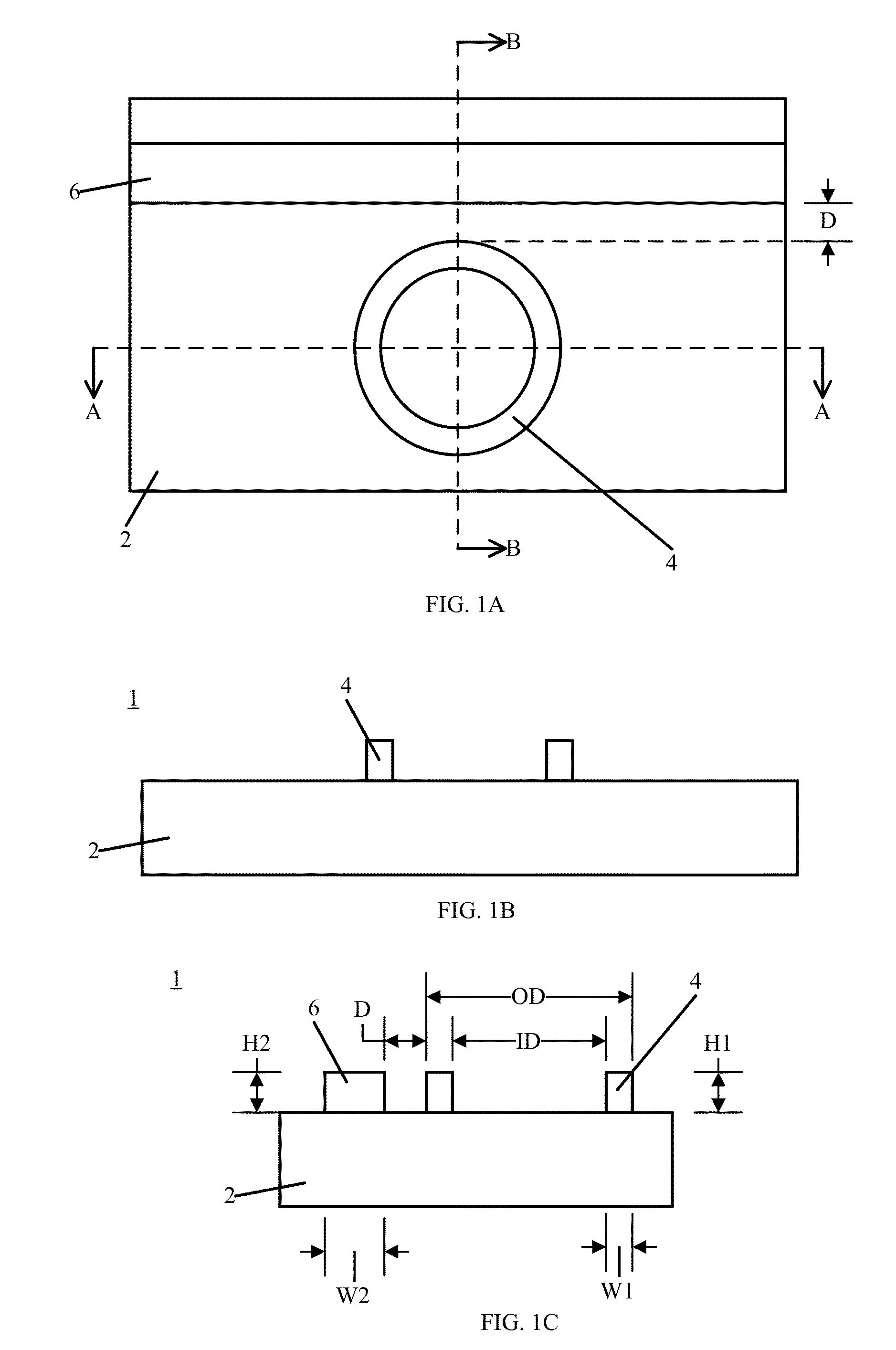
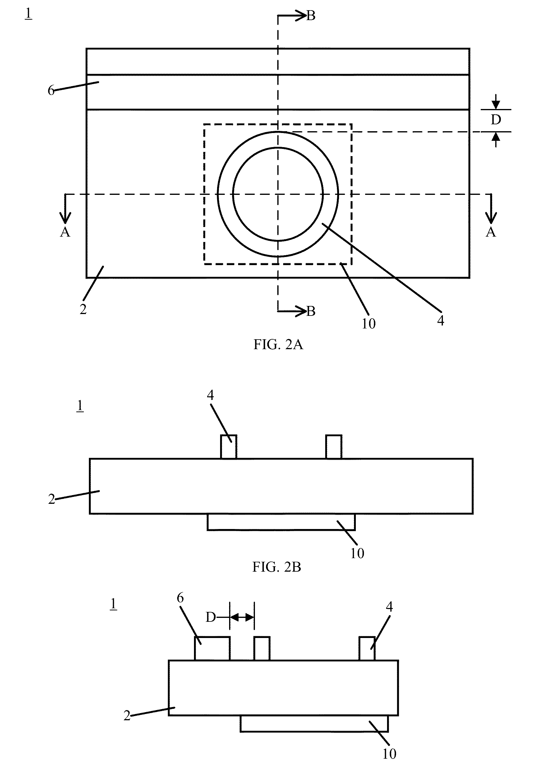
The patent is about a thermometer that can determine a temperature by measuring the change in an optical resonator or the intensity of light transmitted through a waveguide. The thermometer includes a substrate, an optical resonator and a waveguide. The optical resonator is designed to resonate at a specific frequency and can change its resonance as the temperature changes. The waveguide receives the input light and transmits it to the optical resonator. The intensity of the output light is either increased or decreased depending on the temperature of the waveguide. By measuring the difference between the input and output light, the temperature can be determined. The technical effect of this invention is to provide a more accurate and reliable way to measure temperature that is not affected by external factors like wind or lighting.

Problems solved by technology

Despite the ubiquity of thermometers, the underlying technology has been slow to advance over the last century.
However, such resistance thermometers are sensitive to mechanical shock that results in a drift in a resistance that requires recalibration of the instrument.

Method used


Image

  • Optical temperature sensor and use of same
  • Optical temperature sensor and use of same
  • Optical temperature sensor and use of same

Examples


example 1

Thermometer

[0089]A thermometer was fabricated using CMOS techniques on a silicon on insulator (SOI) wafer with a 220 nm thick layer of silicon on top of a 2 μm thick buried oxide layer that isolates an optical mode and prevents loss to the substrate. The fabrication of silicon devices was performed through microfabrication and nanofabrication. Masks were made using ultraviolet light at 193 nm for photolithography and were etched to from a waveguide and Bragg coupler. The Bragg coupler provided free space coupling of light in or out of the thermometer at, e.g., 4 dB per Bragg coupler. The thermometer was subjected to thermal oxidation to form a 10 nm thick SiO2 layer thereon to reduce a surface roughness.

[0090]FIG. 19 shows a micrograph of the thermometer 248 that included ring resonator 254 and waveguide 252. The micrograph was acquired a scanning electron microscope. Ring resonator 254 had 10 μm radius and was separated from waveguide 252 by 130 nm. The thermometer had a free spect...

example 2

Temperature Response of Thermometer

[0091]The thermometer from Example 1 was subjected to thermal response testing. A tunable laser provided input light to the ring resonator. A portion of the input light was picked up from the laser output for wavelength monitoring while the balance of the input light, after passing through the thermometer, was detected by a power meter. The thermometer was mounted on a two-axis stage in a two-stage temperature-controlled enclosure. Input from a platinum resistance thermometer from each stage was fed to an input channel of a proportional-integral-derivative controller that drove a thermoelectric cooler. The first stage minimizes global temperature fluctuations inside the enclosure to ±1 K, and the second stage minimized temperature variations at the thermometer to less than 17 mK over 24 hours. A relative humidity (% RH) inside the enclosure was monitored by a humidity meter. Relative humidity levels were changed inside the enclosure by varying a fl...


PUM


Abstract

A thermometer includes a substrate; an optical resonator disposed on the substrate and including an optical resonance, the optical resonator being configured to receive a resonant frequency corresponding to the optical resonance; and a waveguide disposed on the substrate proximate to the optical resonator to receive input light, to communicate the resonant frequency to the optical resonator, and to transmit output light; wherein an aperture is interposed between: the substrate and the optical resonator, the substrate and the waveguide, or a combination comprising at least one of the foregoing, and the thermometer is configured to change the optical resonance in response to a change in temperature of the optical resonator.

Description

CROSS REFERENCE TO RELATED APPLICATIONS[0001]This application claims the benefit of U.S. Provisional Patent Application Ser. No. 61 / 833,567 filed Jun. 11, 2013, the disclosure of which is incorporated herein by reference in its entirety.STATEMENT REGARDING FEDERALLY SPONSORED RESEARCH[0002]This invention was made with United States government support from the National Institute of Standards and Technology. The government has certain rights in the invention.BACKGROUND[0003]Temperature measurements play a central role in numerous areas such as controlling processes in manufacturing, monitoring physiology, and controlling and monitoring environmental conditions in buildings, automobiles, and outdoors. Despite the ubiquity of thermometers, the underlying technology has been slow to advance over the last century. For example, the standard platinum resistance thermometer was developed over a century ago and has undergone limited modifications. Many modern temperature sensors rely on a res...

Claims


Application Information

Patent Timeline
IPC IPC(8): G01K11/00
CPCG01K11/00G02B6/29338G02B2006/12107
Inventor AHMED, ZEESHANSEMANCIK, STEVETAYLOR, JACOB M.FAN, JINGYUNHAFEZI, MOHAMMADXU, HAITANSTROUSE, GREGORY
Owner THE UNITED STATES OF AMERICA AS REPRESENTED BY THE SECRETARY OF THE COMMERCE
Learn More