
Minimizing latency from peripheral devices to compute engines

a technology of compute engine and peripheral device, applied in computing, instruments, electric digital data processing, etc., can solve the problems of affecting the performance of the application, and affecting the execution speed of the application, so as to reduce the implementation latency, reduce the latency, and minimize the latency

Active Publication Date: 2014-10-23
ADVANCED MICRO DEVICES INC
View PDF5 Cites 5 Cited by
  • Summary
  • Abstract
  • Description
  • Claims
  • Application Information

AI Technical Summary

Benefits of technology

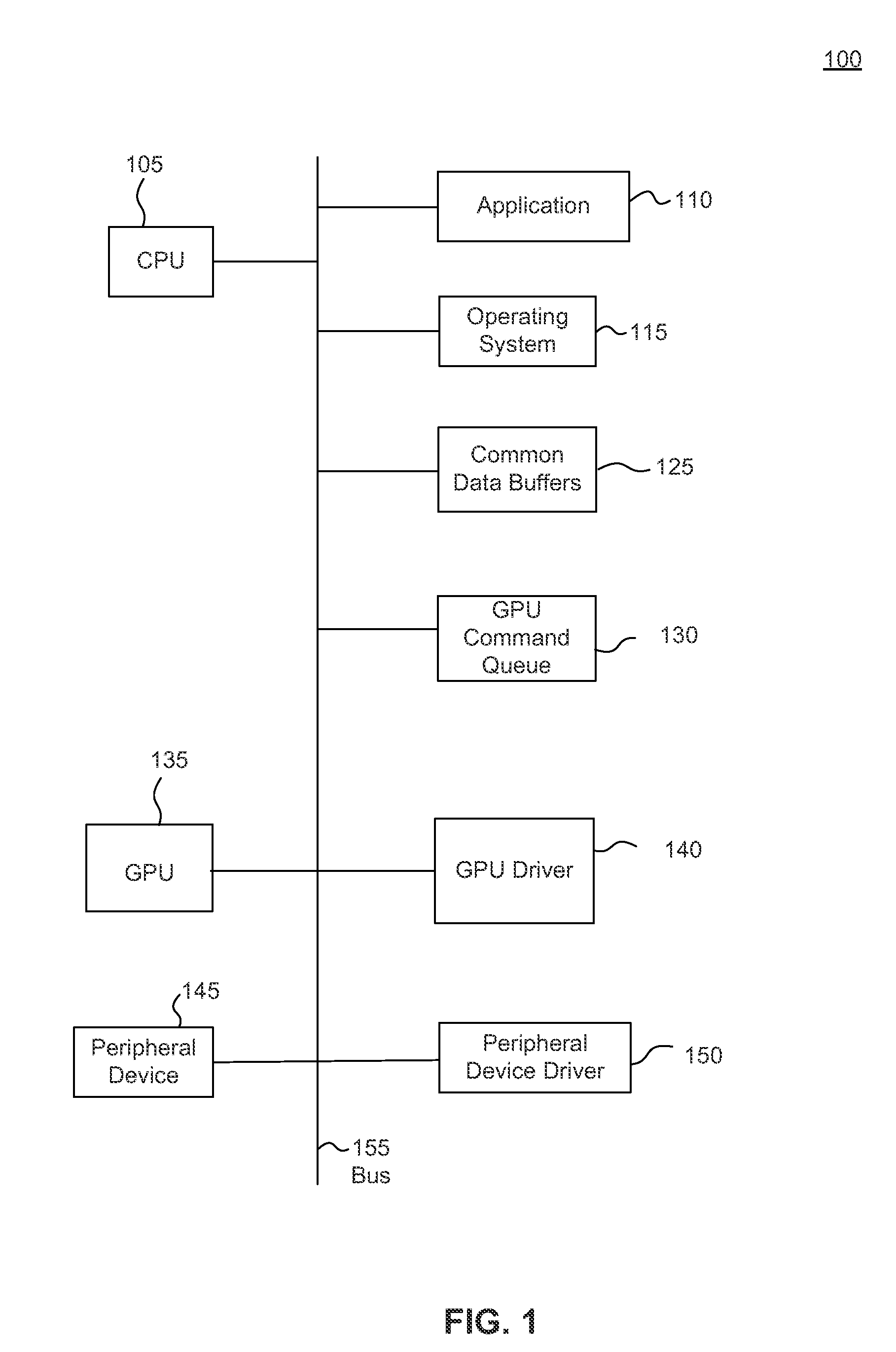
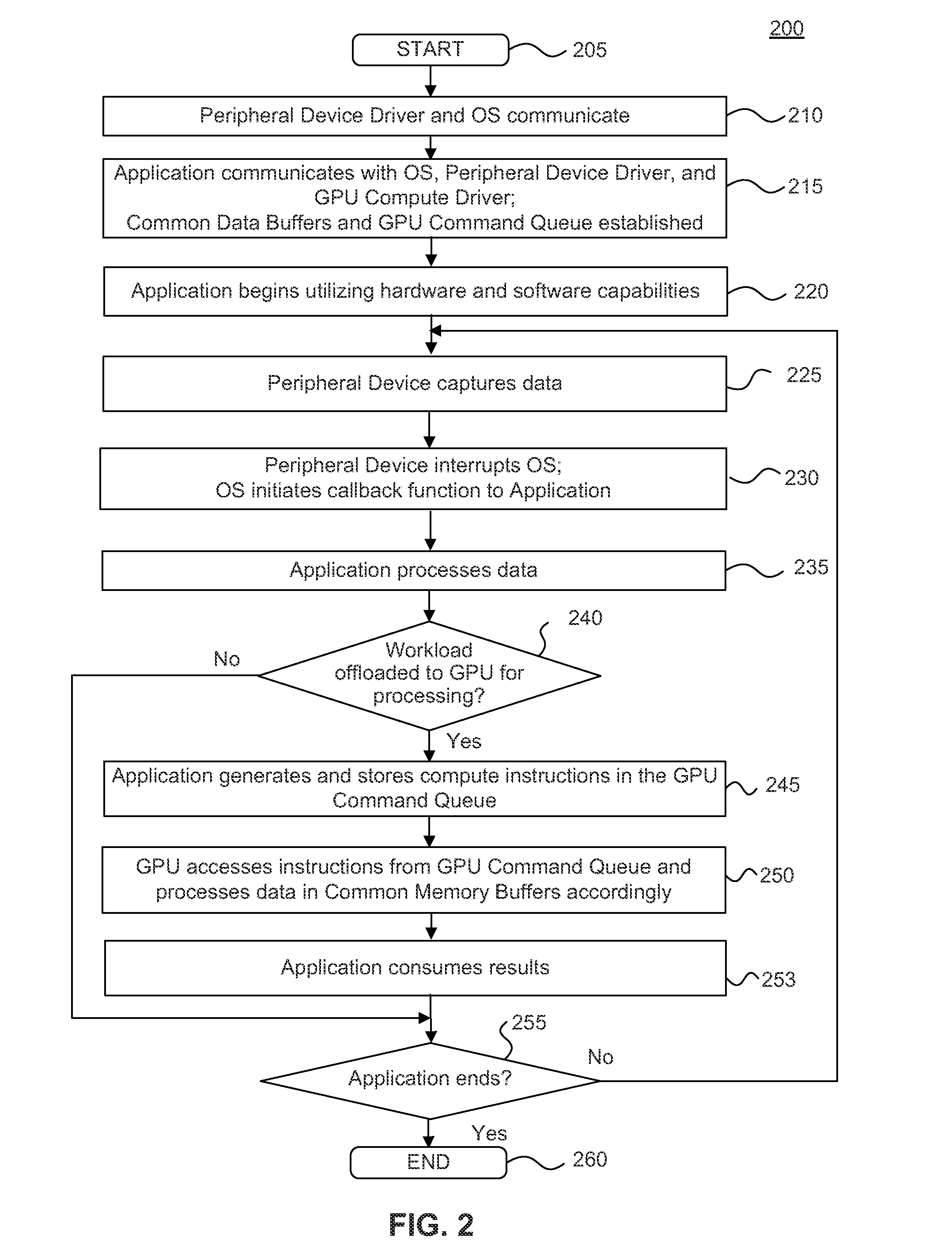
This patent is about a system, method, and computer program that can reduce the delay when using a peripheral device (a capture device) and a compute device (a device that processes the captured data) in a computing environment. This allows for real-time, low-latency applications, such as touch-free human-computer interface (HCI) applications, in an optimal way. In this system, the devices are tightly integrated at the hardware level, and pre-packaged, precompiled compute code is added to the firmware of both the peripheral device and the compute device. This integration minimizes application-level interactions and adds intelligence to the firmware. The peripheral device can capture data and provide instructions and data to the compute device via a common memory pool. Overall, this system reduces latency and allows for improved performance and user experience.

Problems solved by technology

For example, when video data is captured by a camera, there is a noticeable time delay before the captured video is processed by the application and visual feedback is displayed on a screen of a computing device to the user.
The excessive latency, degrades performance, forces users to slow down to try to preserve manipulative stability, and the outcome becomes unpredictable.
The variable CPU response time is a significant source of latency in application performance that is not acceptable to users.

Method used


Image

  • Minimizing latency from peripheral devices to compute engines
  • Minimizing latency from peripheral devices to compute engines
  • Minimizing latency from peripheral devices to compute engines

Examples


Embodiment Construction

[0021]The following detailed description refers to the accompanying drawings that illustrate exemplary embodiments. Other embodiments are possible, and modifications can be made to the embodiments within the spirit and scope of the disclosure. Therefore, the detailed description is not meant to limit the scope. Rather, the scope is defined by the appended claims.

[0022]It would be apparent to one of skill in the art that the embodiments, as described below, can be implemented in many different embodiments of software, hardware, firmware, and / or the entities illustrated in the figures. Any actual software code with the specialized control of hardware is not limiting. Thus, the operational behavior will be described with the understanding that modifications and variations of the embodiments are possible, and within the scope and spirit of the disclosure.

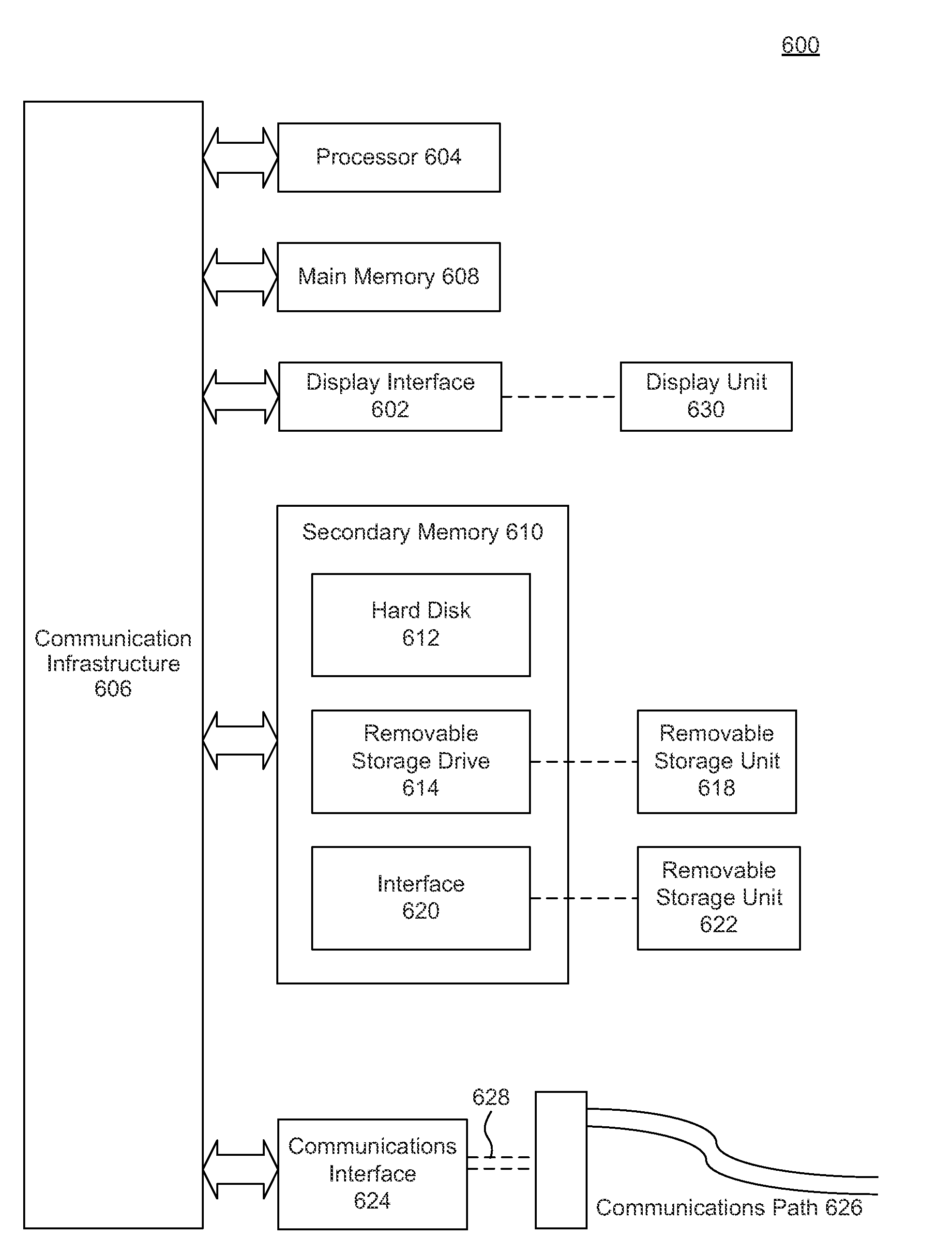
[0023]Computing devices process data and provide many applications to users. Example computing devices include, but are not limited to...


PUM


Abstract

Methods, systems, and computer program products are provided for minimizing latency in a implementation where a peripheral device is used as a capture device and a compute device such as a GPU processes the captured data in a computing environment. In embodiments, a peripheral device and GPU are tightly integrated and communicate at a hardware / firmware level. Peripheral device firmware can determine and store compute instructions specifically for the GPU, in a command queue. The compute instructions in the command queue are understood and consumed by firmware of the GPU. The compute instructions include but are not limited to generating low latency visual feedback for presentation to a display screen, and detecting the presence of gestures to be converted to OS messages that can be utilized by any application.

Description

FIELD[0001]The disclosure is generally directed to computing operations performed in a computing system, and more particularly, to reducing latency from peripheral devices to compute engines in a processing unit.BACKGROUND[0002]A computing device generally includes a processing unit (e.g., a central processing unit (CPU), a graphics processing unit (GPU), accelerated processing units (APU), or the like), system memory controlled by an operating system (OS), and a display device. Users of the computing device demand high quality graphics and real-time (i.e., ideally zero latency) interactions to be rendered on a display and increasingly faster performance of application programs executed on the computing device. The computing device may be embodied in a traditional personal computer (desktop or notebook), mobile device (tablet, smart phone, e-reader) or embedded in a larger system (e.g., a kiosk, vehicle, etc.)[0003]A peripheral device (e.g., a camera module) connected to the computi...

Claims


Application Information

Patent Timeline
IPC IPC(8): G06F13/12
CPCG06F13/12G06F3/14G06F3/017G09G2354/00G09G2360/08G06F13/122G06F13/4072G06F3/0611G06F3/0659G06F3/0685
Inventor WONG, DANIEL W.
Owner ADVANCED MICRO DEVICES INC
Learn More