
Hardware simulation controller, system and method for functional verification

a controller and hardware simulation technology, applied in the field of microprocessor operations and architecture, can solve the problems of inefficient simulation of hardware description language, inefficient processing, and difficult simulating hardware description languag

Active Publication Date: 2014-09-18
SIEMENS PROD LIFECYCLE MANAGEMENT SOFTWARE INC
View PDF1 Cites 43 Cited by
  • Summary
  • Abstract
  • Description
  • Claims
  • Application Information

AI Technical Summary

Benefits of technology

The patent text discusses the use of hardware description language (HDL) to simulate the operation of electronic circuits. However, simulating HDL can be slow and inefficient, especially on modern PC hardware. The technical problem addressed by the patent is to improve and correct the inefficiencies resulting from HDL simulation.

Problems solved by technology

Even the co-simulation usage model, however, results in processing inefficiencies.
Simulating Hardware Description Language can be problematic, especially on modern PC hardware based on x86 server architectures.
In such architectures, Hardware Description Language simulation can be inefficient due to a significant amount of overhead in the representation of the semantic operations of an HDL simulation in the native language.
Additionally, inefficiencies arise from managing the processing of the HDL simulation kernel in software.
As a result, HDL simulation can be expensive in terms of processor time.
One reason is that in x86 server architectures, the representation of HDL logical simulation semantics is large, resulting in large bandwidth requirements.
Another reason is that cache memory is underutilized due to an abundance of non-repeated actions during, for example, a Verilog simulation.
The inability to effectively utilize a memory cache results in slower performance.
Another reason for slowness is poor bus effective utilization in an x86 architecture, due to the fixed size of cache lines.
Thus, significant mismatches between the number of bytes used and the number of bytes read mean that buses are inefficiently utilized.
Additionally, software simulation kernel events and / or scheduling operations are typically not cached well as the ratio of design size to kernel size exceeds 1M to 1.

Method used


Image

  • Hardware simulation controller, system and method for functional verification
  • Hardware simulation controller, system and method for functional verification
  • Hardware simulation controller, system and method for functional verification

Examples


Embodiment Construction

[0043]In the following detailed description, reference is made to the accompanying drawings, which form a part hereof, and in which is shown by way of illustration specific embodiments that may be practiced. It should be understood that like reference numbers represent like elements throughout the drawings. Embodiments are described with sufficient detail to enable those skilled in the art to practice them. It is to be understood that other embodiments may be employed, and that various structural, logical, and electrical changes may be made without departing from the spirit or scope of the invention.

[0044]As explained above, the performance of software-based simulation on modern hardware is hampered by various problems including the size of a compiled design representation in memory, poor instruction and data cache performance, poor memory bus utilization, and a software based simulation kernel. One approach to improving application performance of simulating logic circuits and syste...


PUM


Abstract

Systems and methods of using hardware to simulate software, specifically the semantic operations defined in HDL simulation languages. Traditional software HDL simulation kernel operations of advancing time, activating threads in response to notified events, and scheduling those threads of execution are handled via a simulation controller. The simulation controller is comprised of a timing wheel, an event-processor, a thread / process dispatch engine, a token processor, and a resource-allocator. These components work together with a control logic component to perform the semantic operations of an HDL software kernel.

Description

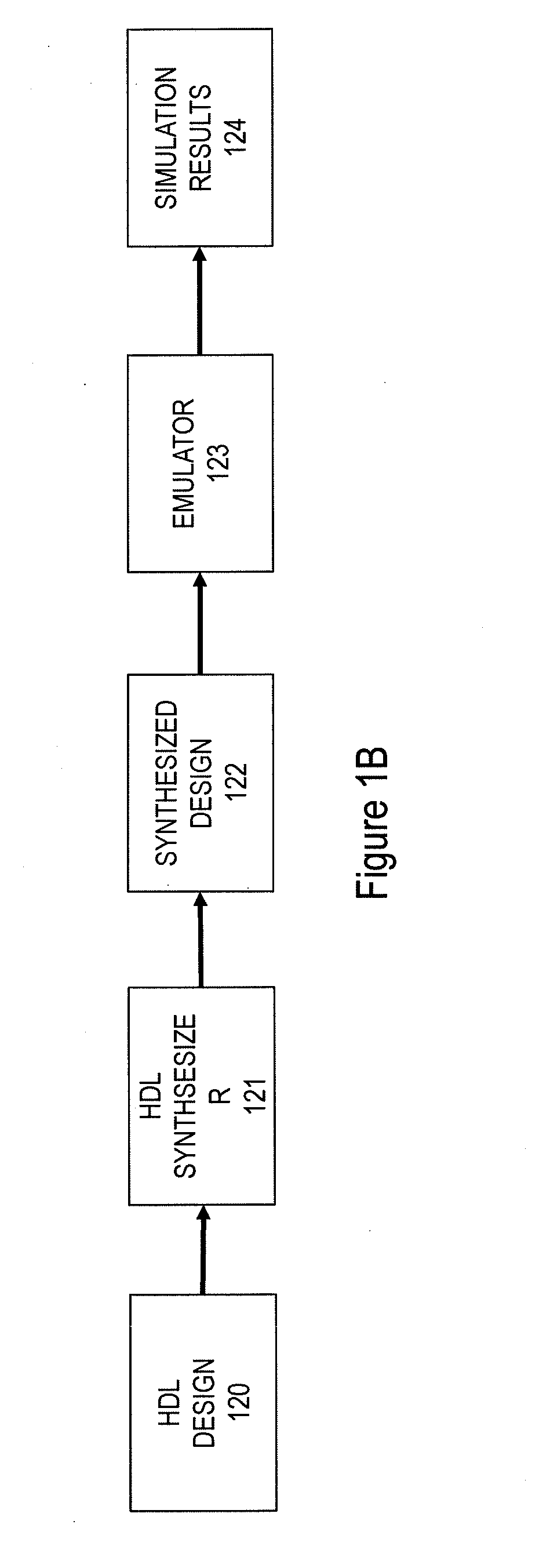
FIELD OF THE INVENTION[0001]The present application relates generally to microprocessor operations and architecture, and more particularly, to systems, methods and apparatus for simulating hardware description language.BACKGROUND OF THE INVENTION[0002]Hardware Description Language or HDL is a specialized computer language used to describe the structure, design and operation of electronic circuits. In general, Hardware Description Language enables precise, formal descriptions of electronic circuits, and is used to automate analysis, simulation, and simulated testing of an electronic circuit. For example, Hardware Description Language is often used to simulate complex circuits such as microprocessors.[0003]Hardware Description Language can be functionally simulated in software. Functional simulation is the use of a computer program to simulate the execution of a second computer program written in a language other than binary machine code. For example, FIG. 1A illustrates a model for f...

Claims


Application Information

Patent Timeline
Patent Type & Authority Applications(United States)
IPC IPC(8): G06F17/50
CPCG06F17/5022G06F30/327G06F30/33G06F30/3308
Inventor STAMNESS, ARTHUR JESSEETSCHEID, BRIANMISUSTIN, RANDY
Owner SIEMENS PROD LIFECYCLE MANAGEMENT SOFTWARE INC
Learn More