
Insulated glazing unit and controller providing energy savings and privacy

a technology of insulated glazing and controller, which is applied in the direction of door/window protective devices, instruments, constructions, etc., can solve the problems of increasing the cost of building operation, increasing the consumption of petroleum products and other non-renewable energy resources, and wasting 5% of the total energy consumed in the united states

Active Publication Date: 2014-09-18
GUARDIAN GLASS LLC
View PDF1 Cites 8 Cited by
  • Summary
  • Abstract
  • Description
  • Claims
  • Application Information

AI Technical Summary

Benefits of technology

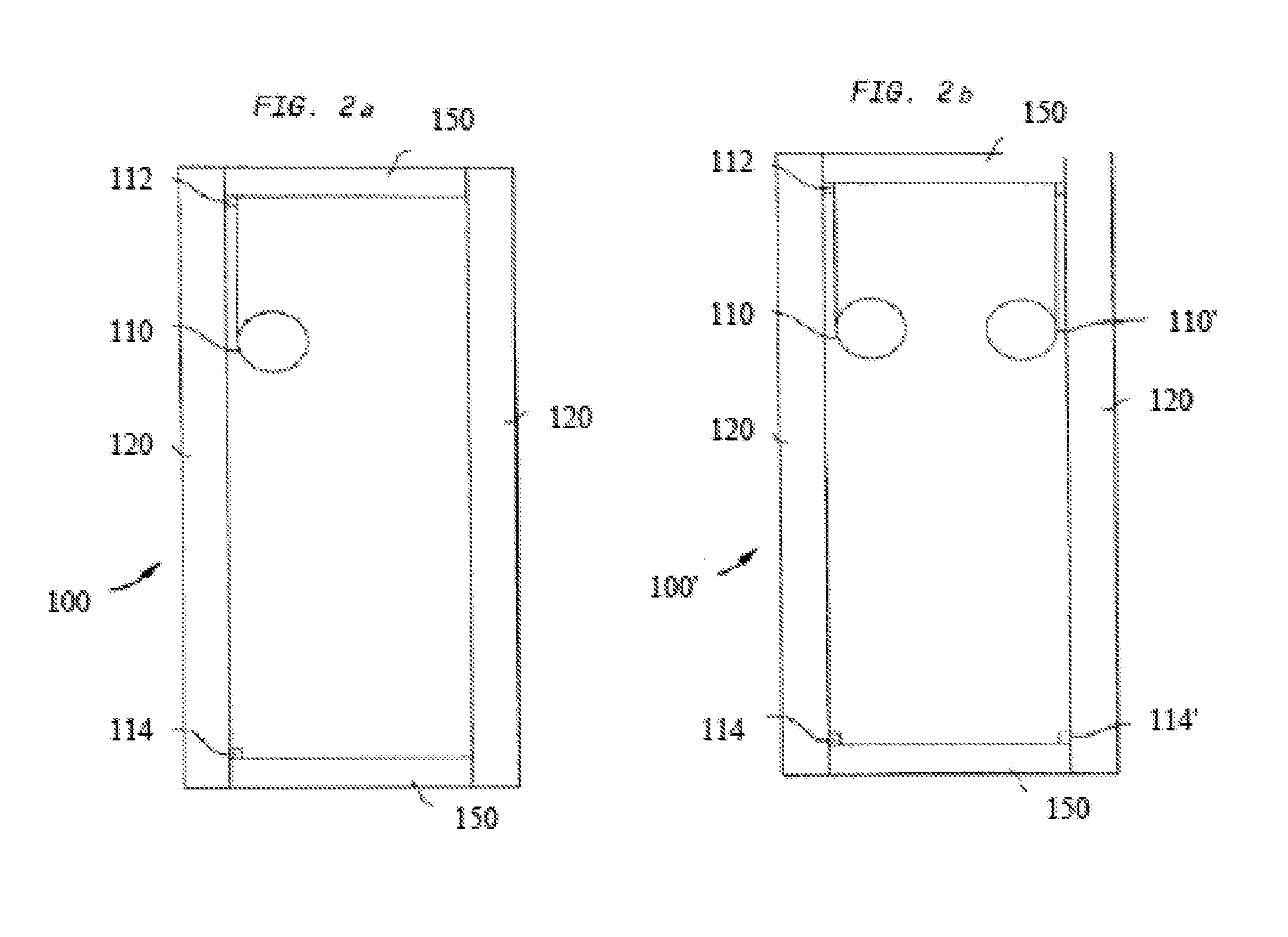
[0009]According to an aspect of the invention, a prior art IGU is equipped with a capillary tube to equalize internal and external pressure at higher altitudes. A hollow metallic spacer, normally filled with a moisture-absorbing component such as a desiccant, is constructed such that the capillary tube feeds an opening in the spacer and another end of the capillary tube is open to the inside of the IGU but sealed with a semipermeable membrane, such as that produced by Gore™, composed of ePTFE. Thereby, when the IGU is raised to an altitude much higher than the one in which it was produced, the capillary tube will allow internal air to escape, normalizing internal and external pressure. When further pressure or temperature changes cause the IGU to take air in from the outside, moisture in the air will be trapped by the desiccant, allowing for long life of the IGU without internal moisture condensation.
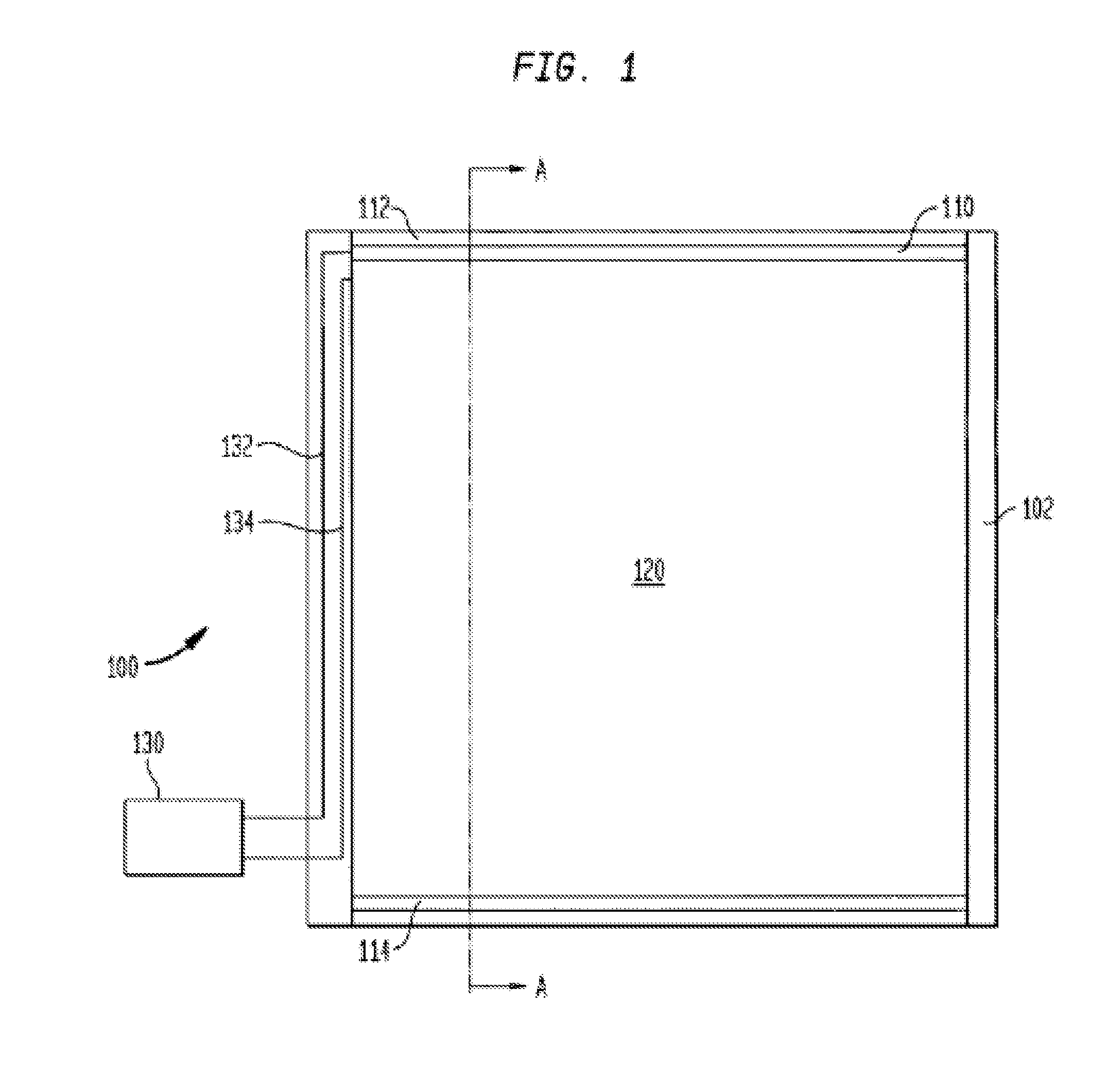
[0013]The controller may include the following functionality to effectively control the one or more shades of an IGU. The controller may include an efficient and fast means for converting input electrical energy to the appropriate drive level and providing the charge needed to extend the shade(s). Such means for converting can include a photoflash capacitor charger or other similar devices. The controller may include a microcontroller unit to provide the algorithms with which to provide the various shade functionalities. The controller may include a means for providing the level shifting needed between the signal level and drive level. Such means for providing can include optical relays, MOSFETs with gate drivers, or other similar devices. The controller may include a means for providing polarity control for the drive signals, such as a multi-phase bridge circuit or other similar devices. The controller may include a means for providing sensing and control of the exact position, speed, and / or motion of the shade(s), such as real time capacitance measurement, closed loop control, or other similar devices.

Problems solved by technology

Glass windows, skylights, doors, and the like, which are used in buildings and other structures, are known to waste 5% of the total energy consumed in the United States.
Residential and commercial building windows permit solar radiation to pass into the interior of the building and cause unwanted heating, particularly during summer months, thus requiring increased use of air conditioning to remove the unwanted heat.
The increased use of air conditioning and heating increases the costs of operating the building and causes increased consumption of petroleum products and other non-renewable energy resources in addition to adding to the initial cost of the structure because of the required HVAC capability.
The increased consumption of these resources has become particularly critical as for example, supplies of petroleum decrease and the price of petroleum rises.
Also, at the same time that this increased consumption has become critical, new constructions of residential and commercial structures incorporate more glass than was used in older construction, thereby further increasing consumption of these non-renewable resources.
However, in spite of their widespread use, the wastage of 5% of the total United States energy consumption still remains.
The fenestration industry uses pressure equalizing structures inside the IGU such as breather tubes and capillary tubes to alleviate this problem, but they are limited in function.
Capillary tubes can shorten the life of the IGU because they eventually allow moisture to penetrate the IGU, and the moisture will eventually condense on the inside glass surfaces.
Undesirably, IG windows that incorporate smart glass are difficult and costly to manufacture, have a questionable operating life, have undesirable operating temperatures, can have very slow response times, provide incomplete darkening, and increase power consumption for their operation.
They are also limited in their ability to provide clear lines of sight for people inside the building.

Method used


Image

  • Insulated glazing unit and controller providing energy savings and privacy
  • Insulated glazing unit and controller providing energy savings and privacy
  • Insulated glazing unit and controller providing energy savings and privacy

Examples


Embodiment Construction

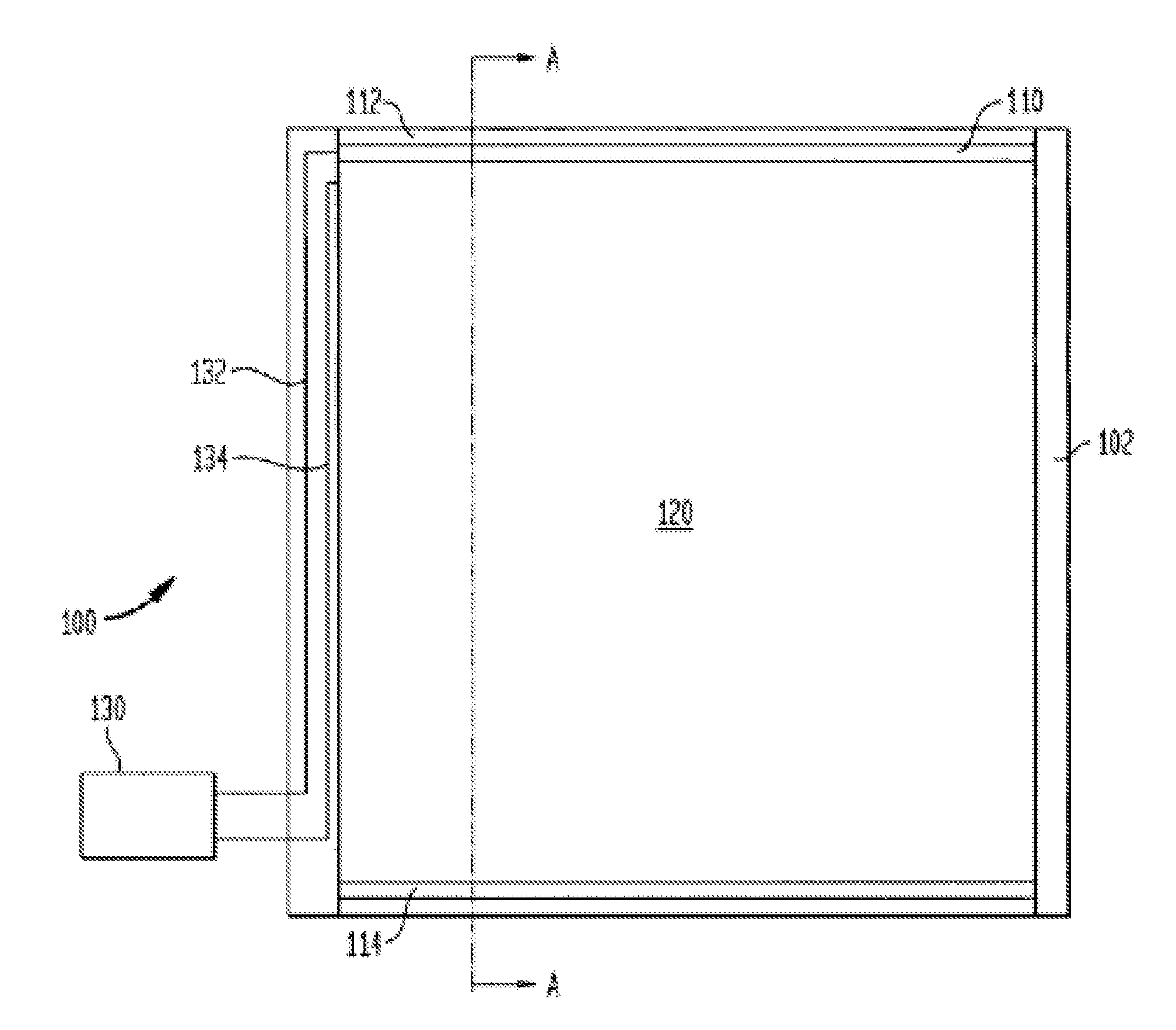
[0062]The present invention overcomes the disadvantages of existing insulated glazing units, such as are used currently in energy efficient windows, by incorporating an electrically controlled, extremely thin physical electropolymeric shade between the glazing panes of the IGU. The shade of the invention provides improvements in functionality, reliability and manufacturability over known shade devices, for example, in the display pixels of existing display (“EPD”) technology, specifically by providing the glazing applications such as are described herein. Known shade devices are described in U.S. Pat. No. 4,266,339 (titled “Method for Making Rolling Electrode for Electrostatic Device” and issued May 12, 1981 to Charles G. Kalt), U.S. Pat. No. 5,231,559 (titled “Full Color Light Modulating Capacitor” and issued Jul. 27, 1993 to Kalt, et al.), U.S. Pat. No. 5,519,565 (titled “Electromagnetic-Wave Modulating, Movable Electrode, Capacitor Elements” and issued May 21, 1996 to Kalt, et al...


PUM


Abstract

An insulated glazing unit includes a spacer defining a framed area, first and second glazing panes attached to the spacer, a pane conductive layer on an inner surface of the first glazing pane, and a dielectric layer disposed on the pane conductive layer. A shade for use with the insulated glazing unit is affixed to the first glazing pane. The shade includes one or more layers selected from a resilient layer, a substantially transparent shade conductive layer, and an opaque shade conductive layer. When an electric drive is applied between the pane conductive layer and the shade conductive layer, a potential difference between the pane conductive layer and the shade conductive layer causes the shade to extend from a retracted configuration to an extended configuration. The shade can further include at least one ink coating layer including pigments that selectively reflect or absorb certain visible colors and infrared.

Description

CROSS-REFERENCE TO RELATED APPLICATIONS[0001]The present application is a continuation of U.S. patent application Ser. No. 13 / 828,125, now U.S. Pat. No. 8,736,938, filed on Mar. 14, 2013, the disclosure of which is incorporated herein by reference.BACKGROUND OF THE INVENTION[0002]The present invention relates to an insulated glazing unit (“IGU”) and more particularly to an IGU which includes an electrically controlled internal shade device that controls the intensity and spectral region of light passing through it, providing both energy efficiency and privacy.[0003]Glass windows, skylights, doors, and the like, which are used in buildings and other structures, are known to waste 5% of the total energy consumed in the United States. Residential and commercial building windows permit solar radiation to pass into the interior of the building and cause unwanted heating, particularly during summer months, thus requiring increased use of air conditioning to remove the unwanted heat. Windo...

Claims


Application Information

Patent Timeline
Patent Type & Authority Applications(United States)
IPC IPC(8): G02B26/02
CPCG02B26/023E06B3/677E06B9/264E06B2009/2643G02B1/16E06B2009/2464E06B3/00E04C2/54G02B26/02
Inventor SCHLAM, ELLIOTTSLATER, MARK S.KOSKULICS, JEFFREY P.FINCH, JOSHUA S.
Owner GUARDIAN GLASS LLC
Learn More