Measurement device and feature measurement method of object to be measured employing same

Active Publication Date: 2014-09-11
MURATA MFG CO LTD
View PDF1 Cites 1 Cited by
  • Summary
  • Abstract
  • Description
  • Claims
  • Application Information

AI Technical Summary

Benefits of technology

The present invention allows for a reduction in the amount of analyte needed for highly sensitive measurement, while also improving throughput and reducing biohazard. Additionally, the use of a detachable and attachable aperture array structure allows for separate measurement without being affected by the analyte or container, resulting in more accurate measurements. Furthermore, a configuration with a single common aperture array structure in multiple cavities reduces measurement errors resulting from dimensional variations among production lots and individuals.

Problems solved by technology

In the method described in Patent Document 2, the capacity of the container for accommodating the liquid and the aperture array structure is typically large, and the necessity of plenty of analyte (liquid) is a problem.
Typically, the liquid and the container reflect or absorb electromagnetic waves, and weakness of a signal of a transmitted electromagnetic wave and complication of analysis of obtained data are problems.

Method used


Image

  • Measurement device and feature measurement method of object to be measured employing same
  • Measurement device and feature measurement method of object to be measured employing same
  • Measurement device and feature measurement method of object to be measured employing same

Examples


first embodiment

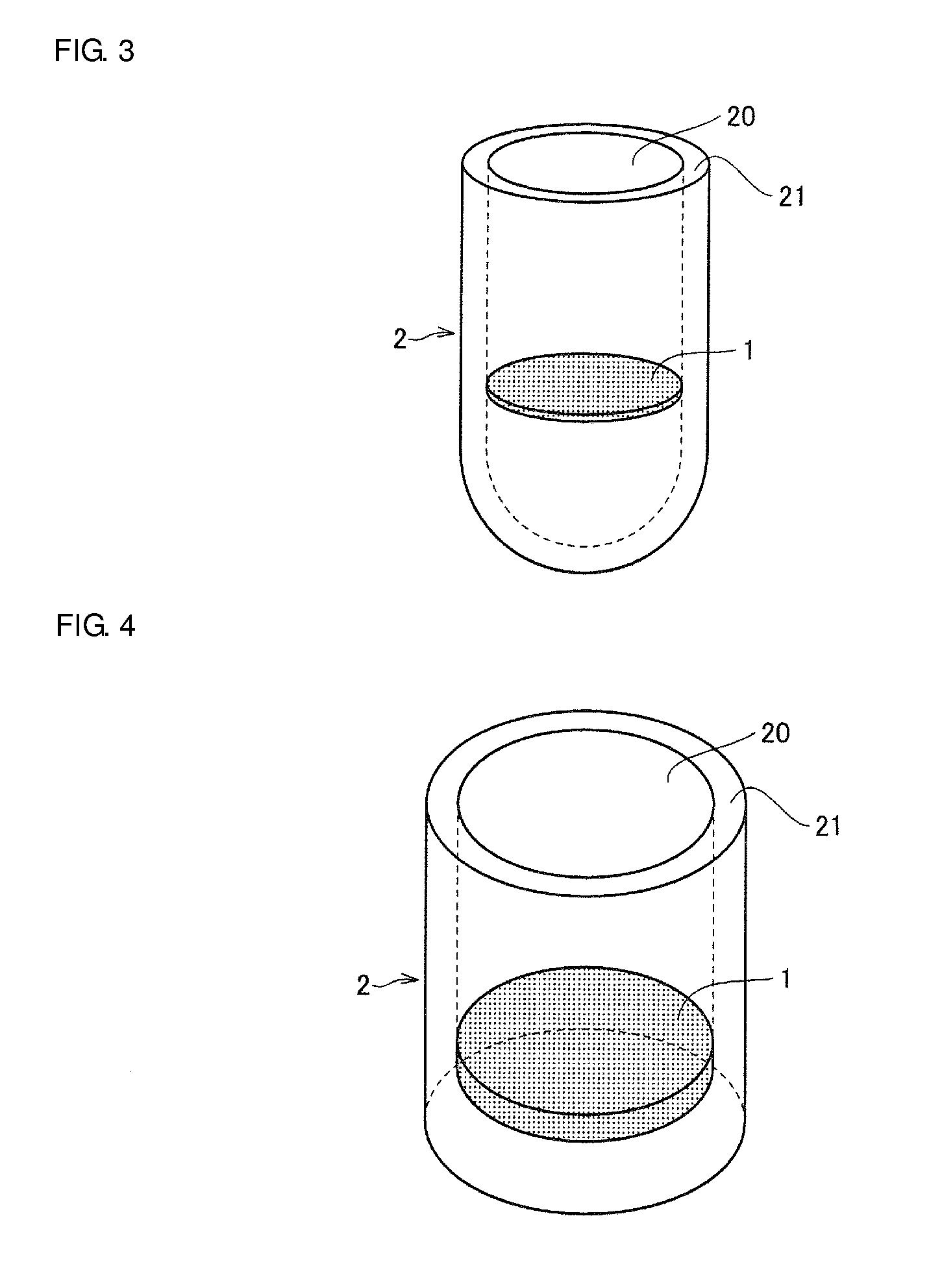
[0077]FIG. 3 is a schematic diagram that illustrates one configuration of the measurement device according to a first embodiment. As illustrated in FIG. 3, the aperture array structure 1 (or part thereof) is arranged in a cavity (well) 20 in a measurement device 2 according to the present embodiment.

[0078]The aperture array structure 1 may preferably be detachable from and attachable to a device main unit 21 including the cavity 20. In that case, measurement can be conducted in a state where the aperture array structure is separated from the analyte or the container, and thus highly sensitive measurement that is not affected by the analyte or the container can be achieved.

[0079]The material of the device main unit (container) 21 may preferably less absorb a used electromagnetic wave. The material of the device main unit (container) 21 may preferably have a small reflectance to the used electromagnetic wave. In those cases, the effects on measurement caused by the device main unit ca...

second embodiment

[0083]FIG. 5 is a perspective view of the measurement device according to a second embodiment. As illustrated in FIG. 5, in the present embodiment, the device main unit 21 includes a plurality of cavities 20 for accommodating liquid containing a specimen, and the cavities 20 are arranged in an array. That configuration enables high-throughput measurement capable of processing a large number of samples and a larger amount of information at a time.

[0084]In FIG. 5, the aperture array structure 1 is disposed between a first member (well bottom component) 211 forming the bottom section of the cavities (wells) 20 and a second member (well upper component) 212 forming the upper section of the wells 20 and is arranged such that the effective regions of the aperture array structure 1 are positioned inside the wells 20. The aperture array structure 1 may be spaced away from the bottom of each of the wells 20, as illustrated in FIG. 3, or may be in contact with the bottom of each of the wells ...


PUM


Abstract

A measurement device that includes a device main unit including at least one cavity for accommodating an analyte containing a specimen and an aperture array structure including a plurality of apertures extending therethrough in a direction perpendicular to a principal surface thereof. The aperture array structure is fixed such that part or all of the aperture array structure is positioned in the cavity.

Description

CROSS REFERENCE TO RELATED APPLICATIONS[0001]The present application is a continuation of International application No. PCT / JP2012 / 060017, filed Apr. 12, 2012, which claims priority to Japanese Patent Application No. 2011-193885, filed Sep. 6, 2011, the entire contents of each of which are incorporated herein by reference.FIELD OF THE INVENTION[0002]The present invention relates to a measurement device and a method of measuring characteristics of a specimen using the same.BACKGROUND OF THE INVENTION[0003]One example of a method for analyzing characteristics of a substance is to hold a specimen on an aperture array structure, radiate the aperture array structure on which the specimen is held with an electromagnetic wave, analyze a transmittance spectrum thereof, and measure the characteristics of the specimen. Specifically, for example, a technique of radiating a metal mesh filter to which a protein that is a specimen is attached with a terahertz wave and analyzing a transmittance sp...

Claims


Application Information

Patent Timeline
IPC IPC(8): G01N21/51
CPCG01N21/51G01N21/253G01N21/3586G01N21/03G01N2021/0346G01N21/3577B01L3/50255G01N2021/3595B01L2300/0618
Inventor KONDO, TAKASHIKAMBA, SEIJI
Owner MURATA MFG CO LTD
Why Eureka
Try Eureka