
GNSS antennas

a technology of gnss antennas and antennas, applied in the direction of resonant antennas, substantially flat resonant elements, radiating element structural forms, etc., can solve the problems of narrow bandwidth, interference with receiver performance, and general unsuitability for high-adjustment applications, and achieve the effect of moderate bandwidth and low loss

Inactive Publication Date: 2014-09-04
HEMISPHERE GNSS
View PDF2 Cites 22 Cited by
  • Summary
  • Abstract
  • Description
  • Claims
  • Application Information

AI Technical Summary

Benefits of technology

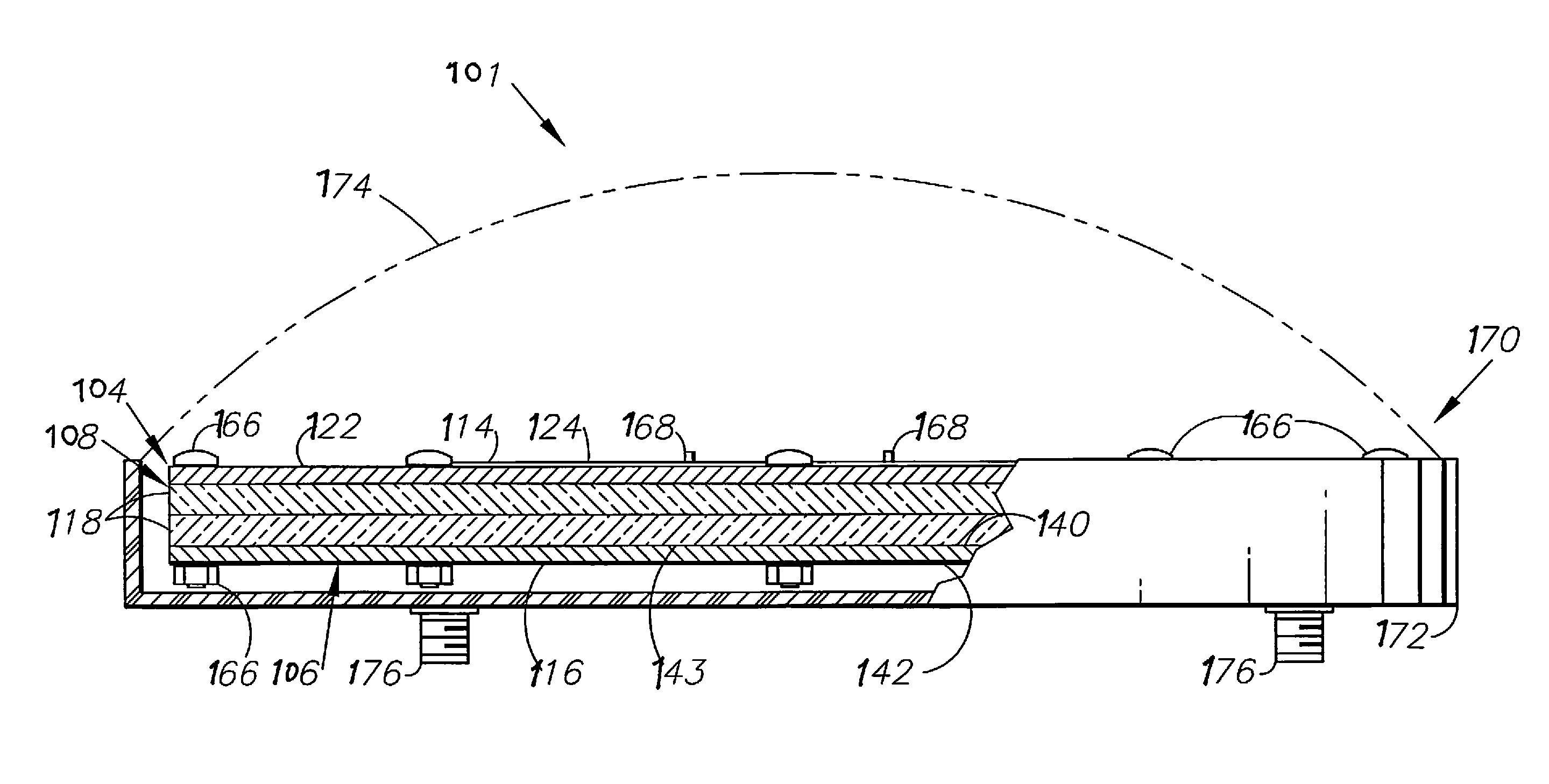
The present invention describes GNSS antenna configurations using PTFE materials in the dielectric layer, which result in lower loss and a moderate bandwidth for multiple GNSS frequencies and augmentation signals. The antenna includes a patch antenna with a thin circular board and a cross-pattern of four lines of holes radiating at 90° intervals from a center point, a PTFE dielectric layer with cross-slots, a ground plane board with microstrip conductors, and a four-port hybrid combiner. The technical effects include improved signal quality and efficiency of GNSS antennas.

Problems solved by technology

Antennas with strong gain patterns at or near the horizon are particularly susceptible to multipath signals, which can significantly interfere with receiver performance based on direct line-of-sight (LOS) reception of satellite ranging signals and differential correction signals (e.g., DGPS).
Ceramic patch designs are of compact size and have the benefit of low cost, but their bandwidths tend to be narrow and they are not generally suitable in high accuracy applications.
The cross dipole antenna has a high gain at low elevation angles and consequently exhibits less desirable multipath performance.
It also has complicated assembly issues.
The pinwheel antenna has generally good performance including the ability to reduce multipath interference, but it is difficult to manufacture compared to other antenna configurations.
This antenna also exhibits good multipath reducing properties and accuracy but its feed circuit is comparatively complicated, consisting of four coaxial probes and three combiners.
There are problems with the use of composite materials as dielectrics including indeterminate homogeneity and consistency.

Method used


Image

  • GNSS antennas
  • GNSS antennas
  • GNSS antennas

Examples


Embodiment Construction

I. Introduction and Environment

[0048]As required, detailed embodiments of the present invention are disclosed herein; however, it is to be understood that the disclosed embodiments are merely exemplary of the invention, which may be embodied in various forms. Therefore, specific structural and functional details disclosed herein are not to be interpreted as limiting, but merely as a basis for the claims and as a representative basis for teaching one skilled in the art to variously employ the present invention in virtually any appropriately detailed structure.

[0049]Certain terminology will be used in the following description for convenience in reference only and will not be limiting. For example, up, down, front, back, right and left refer to the invention as orientated in the view being referred to. The words, “inwardly” and “outwardly” refer to directions toward and away from, respectively, the geometric center of the aspect being described and designated parts thereof. Forwardly ...


PUM


Abstract

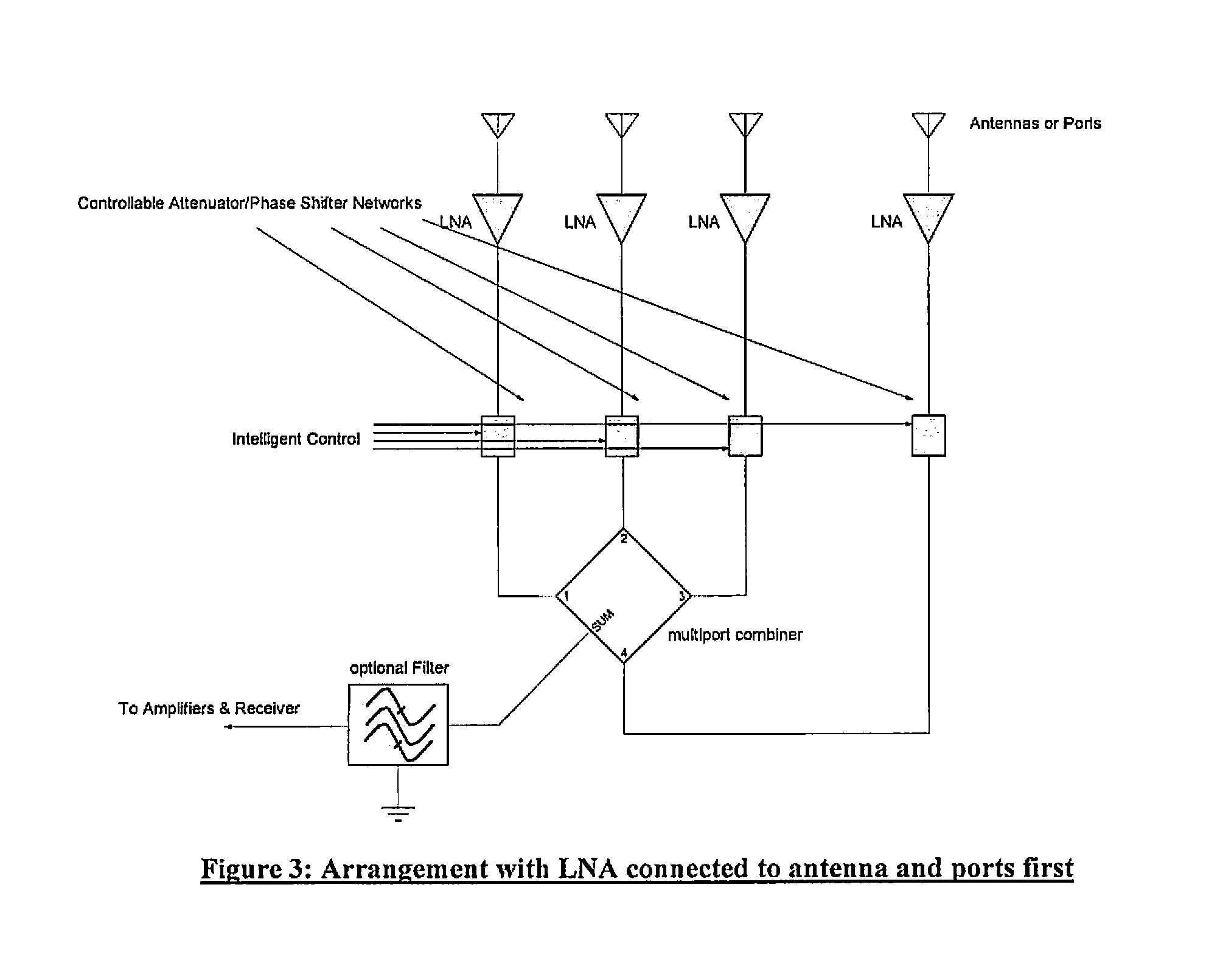
A global navigation satellite system (GNSS) antenna system includes interference mitigation and multipath canceling. Multiple ports or phased arrays of antennas can be provided. Antennas can comprise controlled radiation pattern antennas (CRPA). Crossed dipole and patch antenna configurations can be utilized.

Description

CROSS-REFERENCE TO RELATED APPLICATIONS AND PATENT[0001]This application is related to and claims priority in U.S. patent application Ser. No. 61 / 720,915, filed Oct. 31, 2012; Ser. No. 61 / 720,891, filed Oct. 31, 2012; Ser. No. 61 / 720,905, filed Oct. 31, 2012; and Ser. No. 61 / 732,787, filed Dec. 3, 2012, all of which are incorporated herein by reference. U.S. Pat. No. 8,102,325 is also incorporated herein by reference.BACKGROUND OF THE INVENTION[0002]1. Field of the Invention[0003]The present invention relates generally to antennas, and in particular, to broadband antennas which are particularly well-suited for GNSS applications and which include antenna components formed of polytetrafluoroethelyne (PTFE) materials.[0004]2. Description of the Related Art[0005]Various antenna designs and configurations have been produced for transmitting and receiving electromagnetic (wireless) signals. Antenna design criteria include the signal characteristics and the applications of the associated e...

Claims


Application Information

Patent Timeline
Patent Type & Authority Applications(United States)
IPC IPC(8): H01Q7/00H01Q9/04
CPCH01Q9/0407H01Q7/00H01Q1/38H01Q3/26H01Q21/065
Inventor DURNAN, GREGORY J.FELLER, WALTER J.
Owner HEMISPHERE GNSS
Learn More