A High Gain Patch Antenna with Reconfigurable Pattern
A patch antenna, high-gain technology, applied in the field of communications, can solve the problems of large antenna gain difference, low antenna gain, large loss, etc.
- Summary
- Abstract
- Description
- Claims
- Application Information
AI Technical Summary
Problems solved by technology
Method used
Image
Examples
Embodiment 1
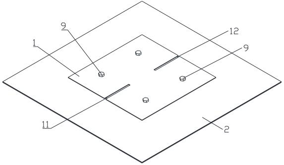
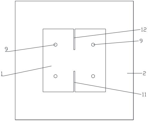
[0030] see Figure 1 to Figure 5 , a high-gain patch antenna with a reconfigurable pattern, including a sequentially stacked metal floor 2, a first dielectric layer, a metal sheet layer, a second dielectric layer, and a layer for forming a TM20 Die and TM 21 The radiation patch 1 of the mold; also includes a first probe 4 and a second probe 5; the metal sheet layer is provided with a first metal sheet 6 and a second metal sheet 7; the first probe 4 is directed to the The first metal sheet 6 feeds power, and the second probe 5 feeds power to the second metal sheet 7; both the first metal sheet 6 and the second metal sheet 7 are coupled to the radiation patch 1 ; The position of the same straight line of the radiation patch 1 is provided with a first slit 11 and a second slit 12, and the length directions of the first slit 11 and the second slit 12 are all in line with TM 20 The direction of the current vector of the mode is parallel; the first metal sheet 6 and the second meta...
Embodiment 2
[0033] On the basis of the structure of the above embodiment, the straight line passes through the center of the radiation patch 1 and is the central axis of the first slit 11 and the second slit 12; the distance between the first slit 11 and the second slit 12 The end of the second slot 12 extends to the edge of the radiation patch 1, and the end of the second slot 12 away from the first slot 11 also extends to the edge of the radiation patch 1, so that the performance of the antenna is better.
Embodiment 3
[0035] On the basis of the structure of the above embodiment, the straight line is parallel to the long side of the radiation patch 1; the central operating frequency of the antenna is λ; the long side of the radiation patch 1 is A, and the wide side is B; the The length of the first slit 11 is equal to the length of the second slit 12, both are C; the width of the first slit 11 is also equal to the width of the second slit 12, both are D, wherein, 0.5λ≤ A≤λ, 0.5λ≤B≤λ, 0.1λ≤C<0.5λ, 0<D≤0.1λ, A≥B, 2C<A, making the antenna performance better.
PUM
 Abstract
Description
Claims
Application Information
 - R&D
- Intellectual Property
- Life Sciences
- Materials
- Tech Scout
- Unparalleled Data Quality
- Higher Quality Content
- 60% Fewer Hallucinations
Browse by: Latest US Patents, China's latest patents, Technical Efficacy Thesaurus, Application Domain, Technology Topic, Popular Technical Reports.
© 2025 PatSnap. All rights reserved.Legal|Privacy policy|Modern Slavery Act Transparency Statement|Sitemap|About US| Contact US: help@patsnap.com


