
Conformal channel monopole array antenna

a technology of array antenna and channel antenna, which is applied in the direction of individual energised antenna array, resonant antenna, elongated active element feed, etc., can solve the problems of reducing the bandwidth of arrays, and affecting the efficiency of arrays. , to achieve the effect of reducing efficiency, reducing bandwidth, and convenient method of including resistive end load for vswr reduction

Active Publication Date: 2006-08-29
RAYTHEON CO
View PDF13 Cites 9 Cited by
  • Summary
  • Abstract
  • Description
  • Claims
  • Application Information

AI Technical Summary

Benefits of technology

[0004]Embodiments of the invention provide a number of technical advantages. Embodiments of the invention may include all, some, or none of these advantages. For example, in one embodiment, a compact, low-profile antenna has moderate bandwidth and is suitable for line-source arrays. Its gain vs. frequency performance is comparable to spirals and log-periodic slots, but its compact size allows many radiators to be packed together, so that they are less than one wavelength apart at the highest frequency of operation.
[0005]Some applications may accept reduced efficiency at the edges of the operating frequency band. For this extended-frequency coverage, it may still be necessary that the antenna have low voltage standing wave ratio (VSWR), even at the band edges, to prevent oscillations on the line connecting the antenna to the electronic circuitry. For these situations, an antenna according to one embodiment of the invention allows a convenient method for including a resistive end load for VSWR reduction.

Problems solved by technology

Antennas with ultra-wide bandwidth have usually been too large to consider for arrays.
They are also often inefficient because they are backed with absorber-filled cavities.
Still other ultra-wideband antennas such as flared notches are very deep, resulting in unacceptable intrusion into, or protrusion from the supporting structure.
Furthermore, their bandwidth decreases when they are used in arrays.

Method used


Image

  • Conformal channel monopole array antenna
  • Conformal channel monopole array antenna
  • Conformal channel monopole array antenna

Examples


Embodiment Construction

[0013]Embodiments of the present invention and some of their advantages are best understood by referring to FIGS. 1 through 5 of the drawings, like numerals being used for like and corresponding parts of the various drawings.

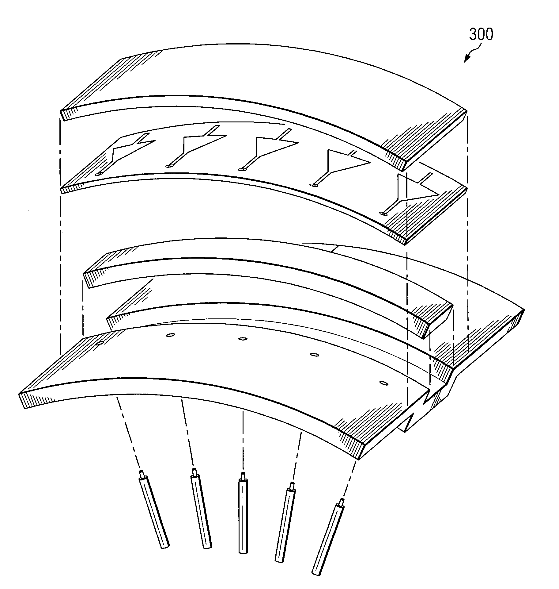
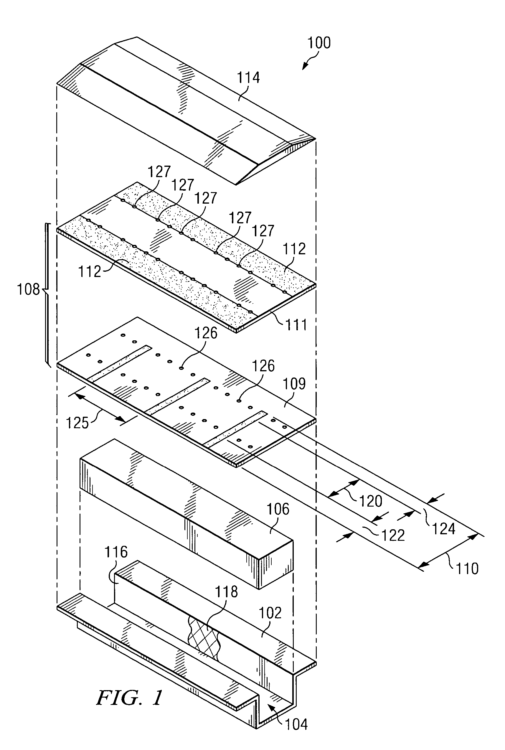
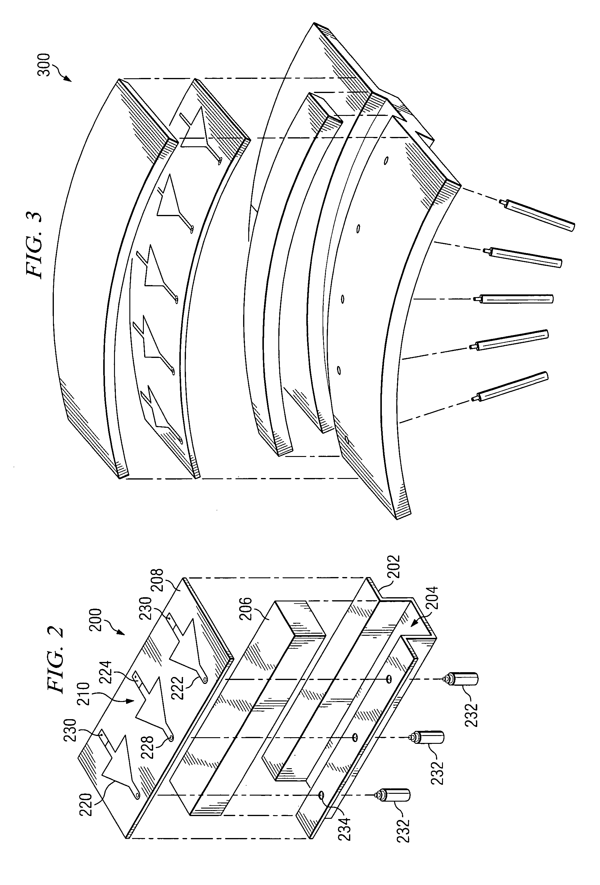
[0014]FIG. 1 is an exploded perspective view of a conformal channel monopole array antenna 100 according to one embodiment of the present invention. In the illustrated embodiment, antenna 100 includes a base plate 102 having a continuous channel 104 formed therein, a dielectric material 106, a substrate 108 comprised of a first layer 109 having a plurality of radiating elements 110 formed thereon and a second layer 111 having a pair of ground planes 112 formed thereon, and a radome 114. The present invention contemplates more, less, or different components than those illustrated in FIG. 1. In addition, other embodiments of antenna 100 are illustrated below in conjunction with FIGS. 2 through 5.

[0015]Base plate 102 may be any suitable size and shape and may be fo...


PUM


Abstract

According to an embodiment of the present invention, a conformal channel monopole array antenna includes a base plate having a continuous electrically conducting channel formed therein, and a substrate coupled to the base plate. The substrate has a plurality of radiating elements formed on a first surface thereof. Each radiating element includes a radiating portion, a feed line, and a resistive end load. The feed lines are configured to couple to respective ones of a plurality of transmission elements.

Description

TECHNICAL FIELD OF THE INVENTION[0001]This invention relates in general to microstrip antennas and, more particularly, to a conformal channel monopole array antenna.BACKGROUND OF THE INVENTION[0002]Antennas with ultra-wide bandwidth have usually been too large to consider for arrays. Examples are spirals and log-periodic slots. They are also often inefficient because they are backed with absorber-filled cavities. The absorber attenuates the received RF power by one-half. Still other ultra-wideband antennas such as flared notches are very deep, resulting in unacceptable intrusion into, or protrusion from the supporting structure. On the other hand, antennas that are compact and amendable to conformal flush-mounting, are usually very narrowband. Examples are cavity-backed slots and microstrip patches. Their bandwidths are typically limited to less than 10%, or 1.1:1. Furthermore, their bandwidth decreases when they are used in arrays.SUMMARY OF THE INVENTION[0003]According to an embod...

Claims


Application Information

Patent Timeline
Patent Type & Authority Patents(United States)
IPC IPC(8): H01Q1/38H01Q1/42
CPCH01Q9/30H01Q21/20H01Q21/12
Inventor MCGRATH, DANIEL T.JOHNSON, RICHARD S.
Owner RAYTHEON CO
Learn More