Method and system for controlling hydroelectric turbines
a technology of hydroelectric turbines and control systems, applied in the direction of dynamo-electric machines, single network parallel feeding arrangements, plates, etc., can solve the problems of differences in water flow velocity, impracticality and uneconomic delivery of power to shore, and high cost of access to turbines installed in the sea, so as to reduce generator losses, reduce the effect of high power factor and minimise the loss of cable to shor
- Summary
- Abstract
- Description
- Claims
- Application Information
AI Technical Summary
Benefits of technology
Problems solved by technology
Method used
Image
Examples
second embodiment
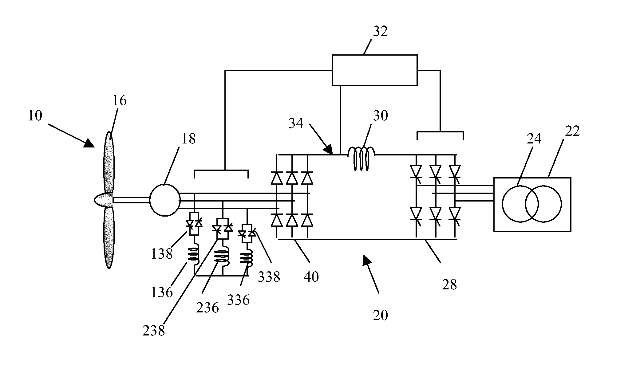
[0093]In a second embodiment, as illustrated in FIG. 4, instead of using very high voltage thyristors, the voltage of each of the three phase AC outputs from the generator 18 may be reduced by connecting each output to an inductive load 136, 236 and 336, provided in parallel with respective inputs of the rectifier of the first-stage converter 26. A reactive current drawn by the inductive load 136, 236 and 336 is arranged to cause a large voltage drop in the winding inductance of the generator 18. The inductive loads 136, 236 and 336 are preferably connected to the rectifier of the first-stage converter by respective solid-state switches 138, 238 and 338 and the rectifier is preferably a plain diode rectifier 40. In this embodiment, the control unit 32 is arranged to adjust the firing angle of the thyristors of the solid-state switch under phase control in order to control the first-stage converter, and therefore the rotation of the turbines 16.
third embodiment
[0094]In a third embodiment depicted in FIG. 5, two three-phase AC power outputs are provided by the generator 18 and are arranged to feed into separate first and second power converter systems 120 and 220, respectively. The outputs of the first and second power converter systems 120 and 220 are arranged to feed separate windings of a common transformer creating a twelve-pulse system which produces significantly lower harmonic current in the transmission system 22, than would be produced by a lower value pulse system. It will be further appreciated that the turbine system 10 of the present invention may employ any number of suitable three-phase groups.
[0095]It will be further appreciated that in the event of a fault occurring in one of the two or more power converter systems 120, 220, the other power converter system(s) could continue to function and allow the turbine 10 to operate with restricted maximum power. In such a case, the control units 32, 32′ are preferably provided with ...
fourth embodiment
[0096]In the present invention, the power converter system 20 of FIG. 3 is replaced with the power converter system 20 of FIG. 6. As illustrated, the power converter system of FIG. 6 also comprises a first-stage converter 26 and a second-stage converter 28. The first-stage converter 26 is arranged to convert AC power supplied by the generator 18 to DC power, and the second-stage converter 28 is arranged to convert the DC power to AC power for transmission to the receiving station (not shown).
[0097]As with the converter systems of the previous embodiments, the converter system 20 of FIG. 6 is arranged to communicate with a control unit 32 to receive control signals and to provide the control unit 32 with a measure of power passing through the power converter system 20. To this end, a sensor (not shown) is provided at the DC link 34 to detect and monitor the DC current passing between the first and second-stage converters and to transmit a signal to the control unit 32.
[0098]In this e...
PUM
 Abstract
Description
Claims
Application Information
 - Generate Ideas
- Intellectual Property
- Life Sciences
- Materials
- Tech Scout
- Unparalleled Data Quality
- Higher Quality Content
- 60% Fewer Hallucinations
Browse by: Latest US Patents, China's latest patents, Technical Efficacy Thesaurus, Application Domain, Technology Topic, Popular Technical Reports.
© 2025 PatSnap. All rights reserved.Legal|Privacy policy|Modern Slavery Act Transparency Statement|Sitemap|About US| Contact US: help@patsnap.com


