
Apparatus for Distance Measurement Using Inductive Means

a technology of inductive means and apparatus, applied in the direction of optical radiation measurement, photometry using electric radiation detectors, instruments, etc., can solve the problems of inability to solve real-world problems, bulky apparatus, increase cost, etc., to eliminate ambiguity, accurately detect and locate stress attack points, and eliminate ambiguity

Inactive Publication Date: 2014-08-21
KKB TECH LLC
View PDF2 Cites 8 Cited by
  • Summary
  • Abstract
  • Description
  • Claims
  • Application Information

AI Technical Summary

Benefits of technology

The present invention is a system that can be used to diagnose, prevent, and mitigate damage caused by stress in real-time, using a computer or controller. The system includes a sensor that can be attached to existing insulating and protecting material without disassembly of the conduit, and can be used in conjunction with current visual inspection techniques or non-visual measurement systems. The system also provides a means to determine curvilinear distance to assess damage, which helps avoid safety risks associated with using electricity. Additionally, the measurement does not require removing the conduits that employ the sensor technique. The technical effects of this invention include increased safety and risk reduction, improved accuracy, and the ability to perform in-situ diagnostics and mitigation of stress on objects such as pipelines and electrical harnesses.

Problems solved by technology

The problem of the prior art is its complexity, inability to solve real-world problems, the need for bulky apparatus, and numerical processing of algorithms, which adds weight and increases cost.
Almost all of the said patents do not address detecting stressor attack or calculating the location of where the stress attack is taking place before damage, deterioration, and unsafe condition has occurred.
Prior art that teach single-ended sensing with processing signals of reflected waveforms to determine and locate damage to conduits is limited to un-branched conduits because complex branched conduits have distance ambiguities, since several branches will traverse the same reflected distance.
Use of uncontained electrical signals is often dangerous and hazardous especially when conduits carry flammable or explosive matter, yet currently nothing is in wide use that enables calculating distance damage by un-collimated light means.
Currently nothing is in wide use that teaches unambiguous distance calculation using measurements from a single-ended sensor to locate stressors that will cause damage, or have caused damage to a conduit.
In particular, there is nothing that teaches unambiguous distance calculation using measurements from a single-ended sensor to locate points where heat, strain, or other stressor is causing an unsafe condition in an electrical conduit before an open circuit, or a short circuit, or grounding of a circuit happens.
Patent searches in preparation of this application have not found prior art that provides a means for enabling inexpensive automated distance calculation for location of stressor attack and damage to equipment and conduits that do not rely on electricity means.
Said searches have not found prior art that utilize inductive illumination of translucent media as a means for measuring distance for locating damage to the conduit insulation and, by implication, the conductor therein.
U.S. Pat. No. 4,988,949 by Boenning et al is limited to teaching detecting a short circuit caused by mechanical damage (chafing) on electrical cables against grounded structures under constant monitoring.
Boenning et al does not teach locating the distance to the fault before the short occurs.
Watkins' patent does not teach a means to perform detection of mechanical damage without use of an electrically conductive sensor material.
Watkins' patent does not teach detecting stressor attack, or use of optical measurements, or measuring distance to locate the point of heating.
Haun et al U.S. Pat. No. 6,259,996 and Fleege et al U.S. Pat. No. 6,242,993 teaches arc fault circuit breakers that act to interrupt in real time on detection of arcing electrical faults, but it may be too late to avert disaster.
Haun et al do not teach how to calculate curvilinear distance to the arcing electrical fault.
Patents dealing with diagnosing arc and ground faults have limitation because they do not assist detection of the stress attack before the arc or ground fault problem occurs and do not assist repair people in locating the place of where the problem occurs in order to correct the situation and any damage caused.
It is a limitation when prior art such as Hiller U.S. Pat. No. 5,218,307 and Miskimins U.S. Pat. No. 6,230,109 that require manual intervention when inspecting electrical and conduits of hazardous materials for finding defects and failures.
Furse et. al. does not teach how to calculate distance to damage in non-metallic materials that surround and / or protect a conduit.
Blemel does not teach accurately calculating the curvilinear distance to the point of damage.
Weiss but does not teach using light to measure length of the fiber receiving the induced light.
In the June 2013 article, “Automatic Detection of Optical ‘Faults’ in Communications Networks,” (incorporated in its entirety by reference above, Bartur states: “Today there is no proven method for automated monitoring of the optical fiber cable plant in the aggregation and data center segments of private campus or public communications networks.
Metrics at the higher network layers may identify that a problem exists, but they cannot quickly isolate the location of an optical fiber fault nor can they automatically trigger the immediate dispatch of repair technicians.
In the case of aircraft wiring and conduits conducting dangerous chemicals, such damage detected before the stressor affects the performance of the conduit could mean the difference between life and death.

Method used


Image

  • Apparatus for Distance Measurement Using Inductive Means
  • Apparatus for Distance Measurement Using Inductive Means
  • Apparatus for Distance Measurement Using Inductive Means

Examples


embodiment

Preferred Embodiment

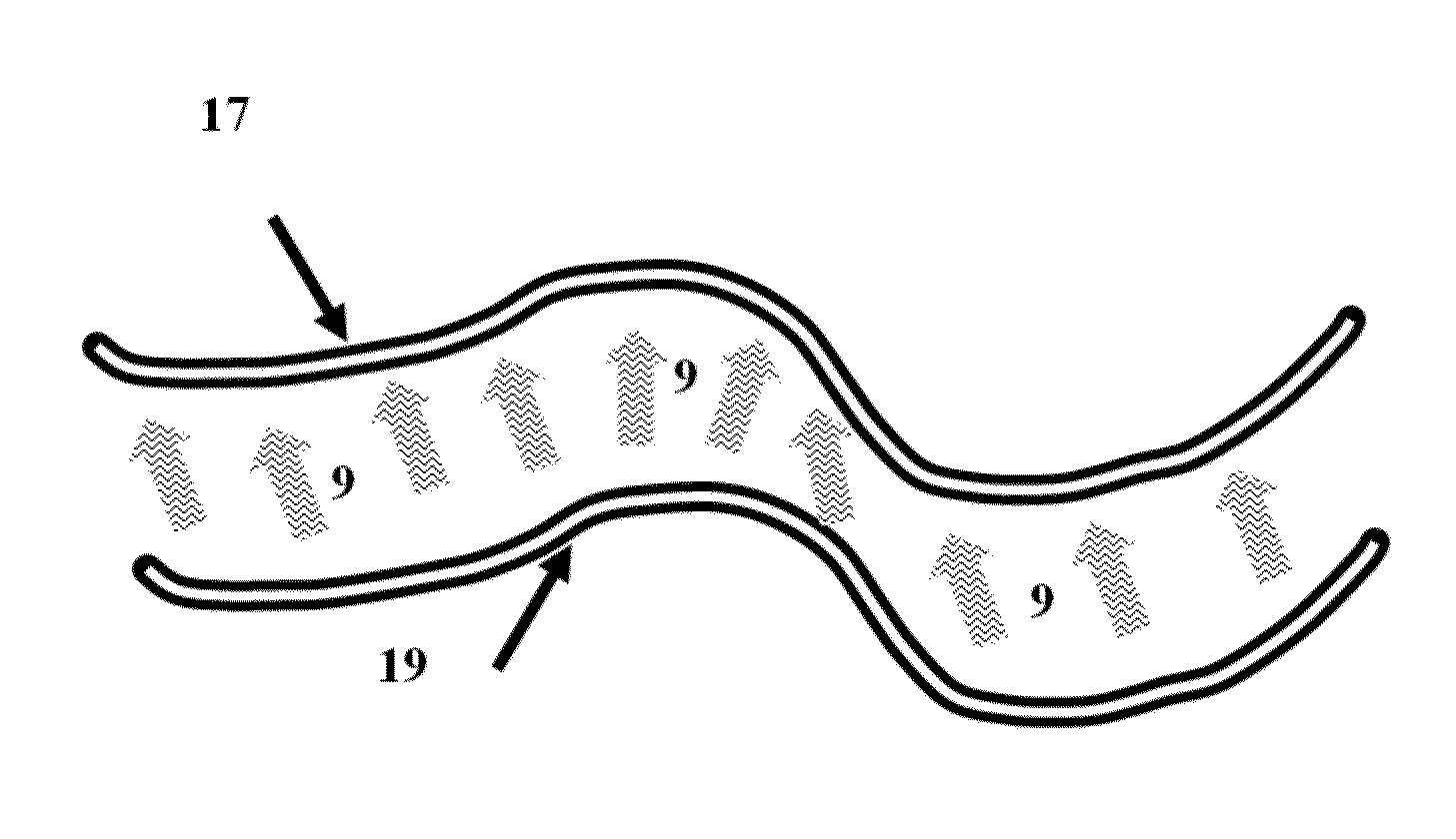
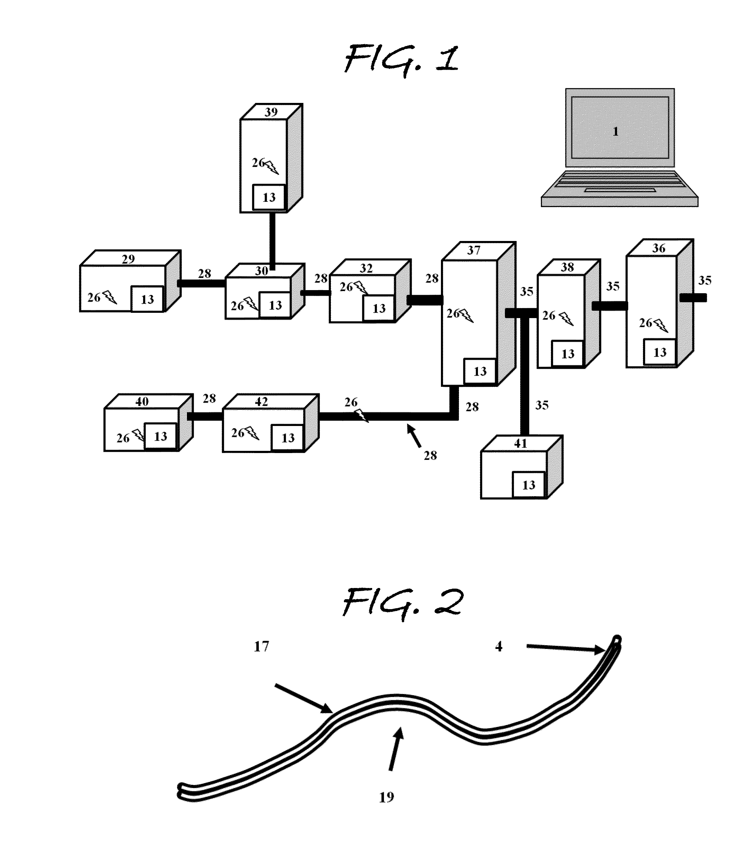
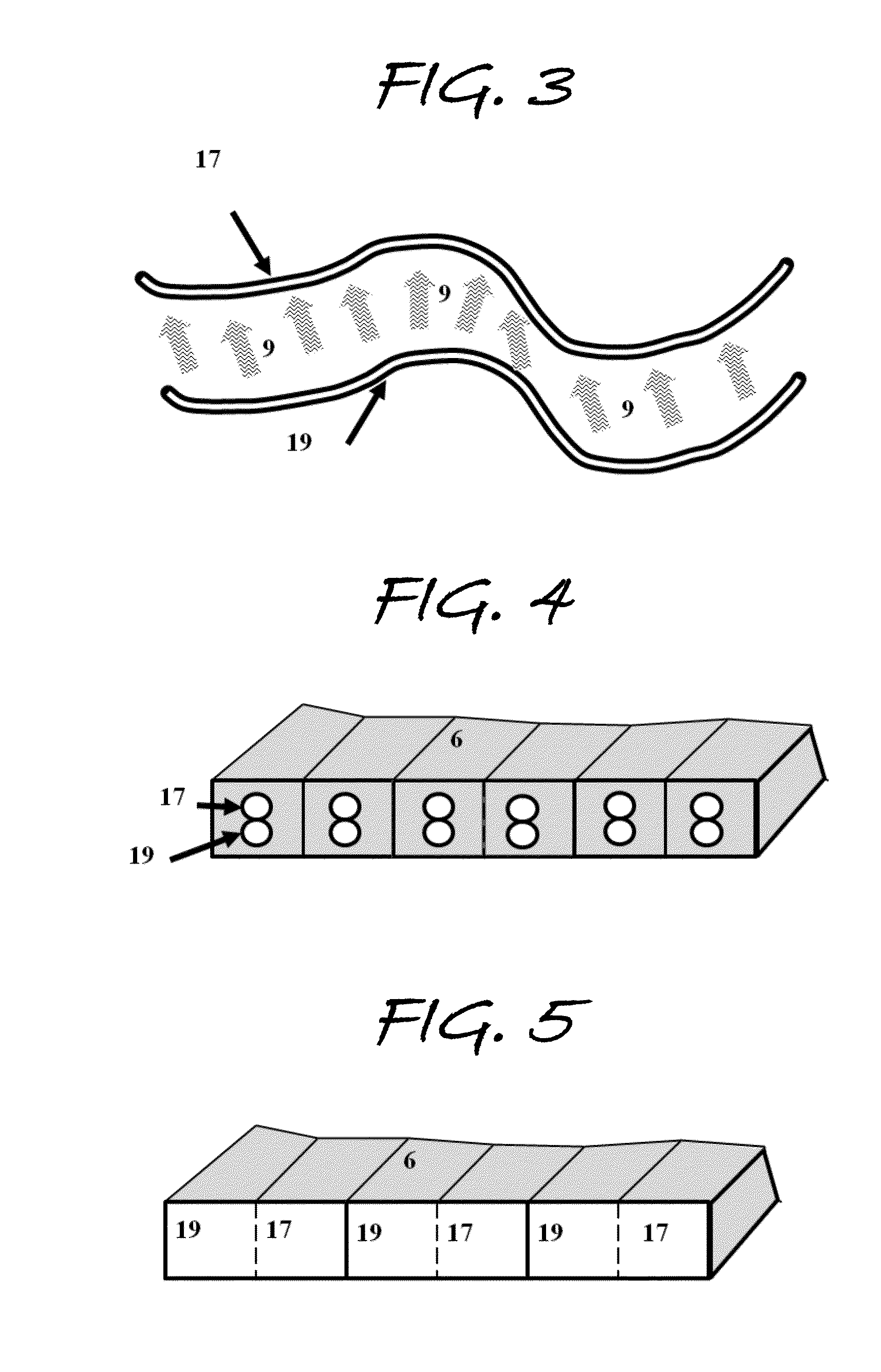
[0211]In a best embodiment, there is at least one controller with integral processor, or other processor coupled to a control means. There is at least one light source coupled to at least one sensor, which comprises one or more emitters constructed with elongated translucent media that guide the emitted light. There is at least one receptor constructed with one or more strands or pieces of translucent media that guide light. The receptor is parallel and proximal to at least one emitter so as to receive along its length light flux emitted axially from at least one emitter. Ideally, a proximal emitter and receptor are encased and protected by an opaque cladding to keep artificial light or daylight from entering the receptor. Further, the receptor guides the light within to a photodetector that: 1) outputs signal information proportional to intensity of light flux guided by the receptor; and 2) communicates the signal information to at least one controller or other ...


PUM


Abstract

A system that provides detection, annunciation, mitigation, and alleviation of stress attacks by executing algorithms based on measurement of intensity of light. The system determines to execute algorithms to take programmed action based on potential effects of a detected stress attack. The system can be used, for example, to determine the position of potential attacks to conduits that transport electricity, oil, gas, foodstuffs, water, people, and materials.

Description

CROSS-REFERENCE TO RELATED APPLICATIONS[0001]The present application claims the benefit of Applicants' prior Provisional Patent Application No. 61 / 850,655, filed on Feb. 21, 2013.STATEMENT REGARDING FEDERALLY SPONSORED RESEARCH OR DEVELOPMENT[0002]Not Applicable.REFERENCE TO SEQUENCE LISTING, A TABLE, OR A COMPUTER PROGRAM LISTING COMPACT DISK APPENDIX[0003]Not Applicable.LIST OF REFERENCED DOCUMENTSU.S. PATENT DOCUMENTSPatent NumberIssue DateInventor6,265,880July 2001Born et al4,988,949January 1991Boenning et al5,862,030January 1999Watkins, et al6,249,230June 2001Baldwin et al5,218,307June 1993Hiller6,868,357March 2005Furse, et. al7,590,496September 2009Blemel7,356,444April 2008Blemel7,277,822October 2007Blemel7,974,815July 2011Blemel7,049,622May 2006Weiss7,763,009July 2010Weiss7,329,857February 2008Weiss6,965,709November 2005Weiss3,074,265January 1963Symons3,610,025October 1971Brunner5,078,432January 1992Seiter5,754,122May 1998Li et al.6,035,717March 2000Carodiskey6,265,880July 20...

Claims


Application Information

Patent Timeline
IPC IPC(8): G01D5/26
CPCG01D5/268G01D5/35345
Inventor BLEMEL, KENNETH GERALDBLEMEL, PETER ANDREWPETERS, FRANCIS EDWARDPETERSON, TODD FRANCIS
Owner KKB TECH LLC
Learn More