Production method of pneumatic tire and pneumatic tire

a production method and tire technology, applied in the field of pneumatic tire and pneumatic tire production, can solve the problems of inflation deformation, large shrinkage in connection with cooling, and shrinkage of unvulcanized tread, and achieve the effect of maintaining productivity and tire performan

Inactive Publication Date: 2014-08-21
SUMITOMO RUBBER IND LTD
View PDF6 Cites 6 Cited by
  • Summary
  • Abstract
  • Description
  • Claims
  • Application Information

AI Technical Summary

Benefits of technology

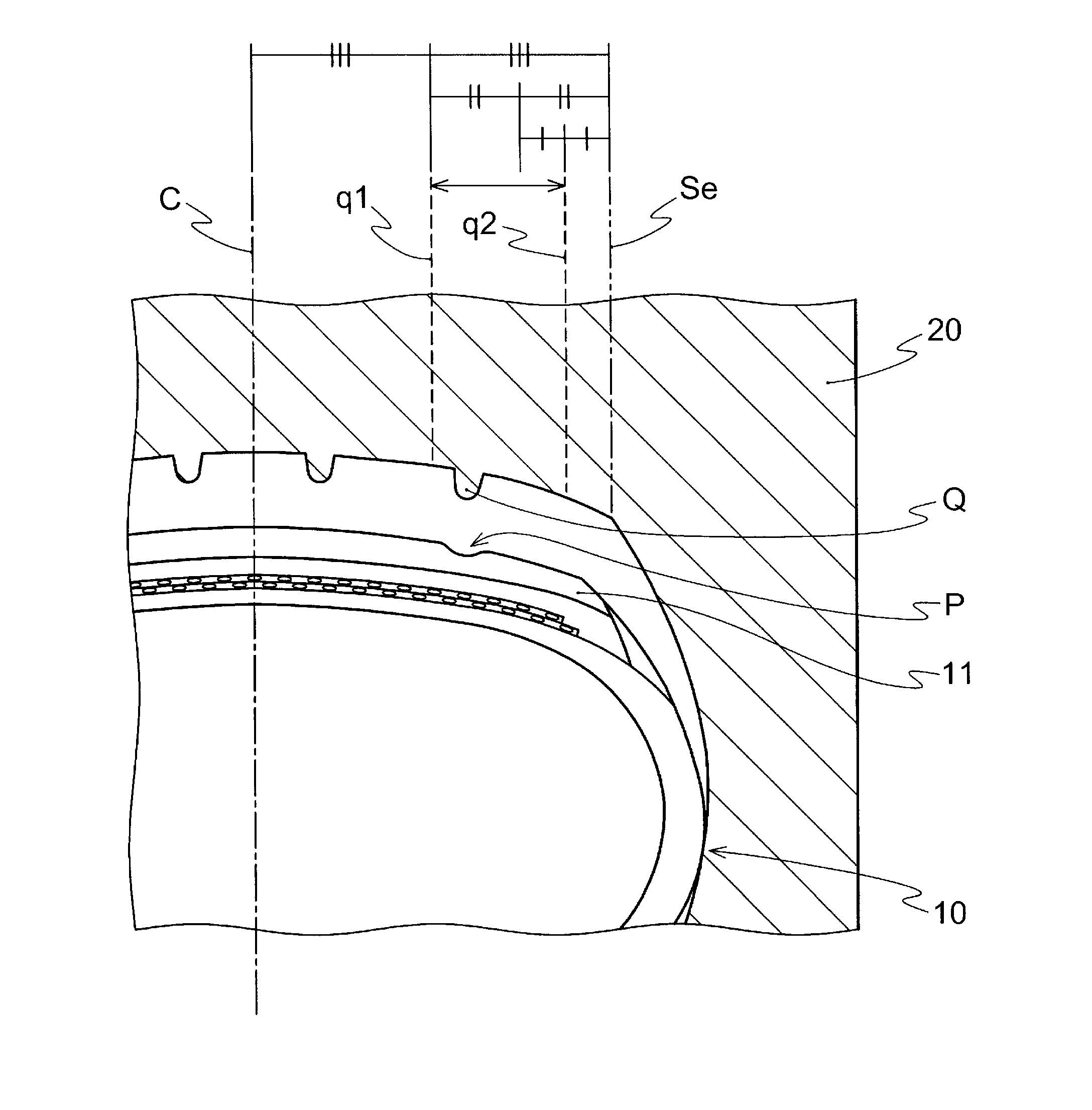
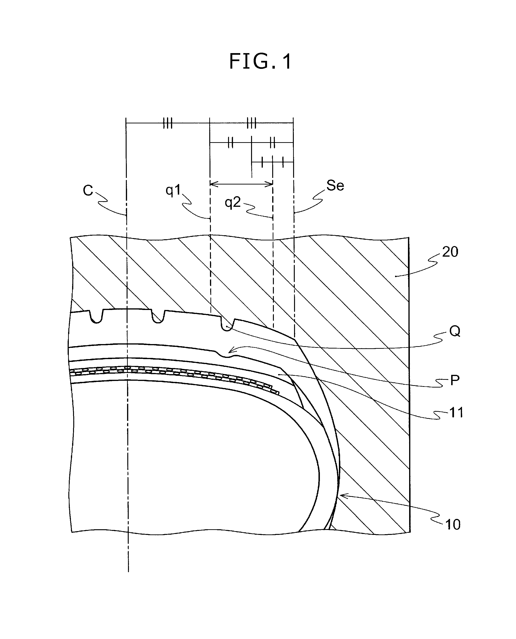
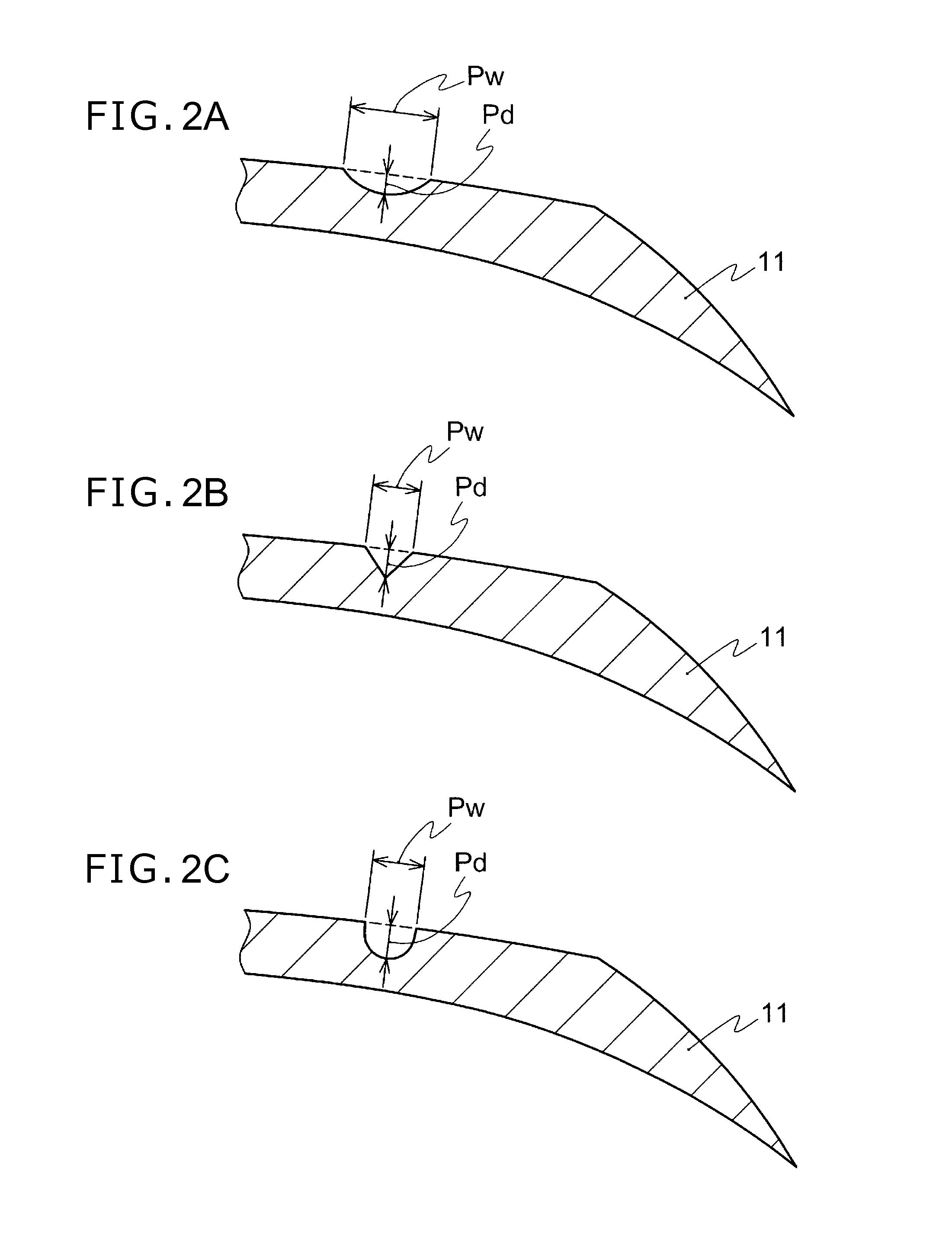
[0020]According to the present invention, a production method of a pneumatic tire where a deformation in the bottom of the shoulder main groove of the tread is decreased, an initial tensile deformation due to inflation is prevented and as a result, a generation of a TGC is prevented while maintaining productivity and tire performance can be provided, by using a rubber composition for a tread comprising 40 to 120 parts by mass of silica which has a BET specific surface area of 70 to 250 m2 / g, and 2.5 to 6 parts by mass of at least one selected from the group consisting of stearic acid; a metal salt of saturated fatty acid and a specific mold release agent, based on 100 parts by mass of the rubber component, and providing, in the molding step (step A) of the unvulcanized rubber composition for a tread, a concave profile in a predetermined size at a position where the convexity for the shoulder main groove of the vulcanization mold is pressed. According to the present invention, a pneumatic tire produced by the production method can be further provided.

Problems solved by technology

That is, the silica which has not been able to couple to the silane coupling agent reaggregates, and thereby a shrink of the unvulcanized tread is caused.
Further, even after this unvulcanized tread is vulcanized in a vulcanization mold, a large shrink is caused in connection with cooling, when compared with the rubber composition in which only carbon black is compounded as a filler.
This shrink in connection with cooling after vulcanization is a cause of an inflation deformation in the bottom of the shoulder groove.
In addition, the shrink is increased due to the compounding of silica since a space existing among silane coupling agent, unreacted silica and a rubber component, or volatile gas existing in the rubber component before vulcanization disappears after vulcanization and cooling.
If the inflation deformation becomes large, the growth of the initial cut generated by stimulus of ozone, light and the like in the bottom part of the shoulder groove is promoted and results in a generation of a tread groove crack (TGC) after repeated deformation in use.
The generated TGC may reach the base tread and / or a breaker layer inside the tread due to repeating deformation in use and may cause a separation, air leakage and a burst of the tire.
However, in the tire in which the shoulder groove is narrowed by inflation, the pressure of the road-contact area of the shoulder portion becomes larger than that of the crown portion due to the protrusion of the shoulder portion towards the road-contact direction, and thereby the tire performance is deteriorated by low high-speed durability and / or increased rubber abrasion on the crown area.
However, it is not easy to cover the total surface area of silica with a silane coupling agent and the problem has not been solved.
Further, though a technique of preventing the inflation deformation and the generation of the TGC by frequently applying a mold release agent on a vulcanization mold under a low temperature and longtime vulcanization to improve the slip of the rubber is known, the productivity thereof is not good and thus is impractical.
However, suppressing deformation in the bottom portion of the shoulder groove is not considered.

Method used


Image

  • Production method of pneumatic tire and pneumatic tire
  • Production method of pneumatic tire and pneumatic tire
  • Production method of pneumatic tire and pneumatic tire

Examples


examples

[0112]Though the present invention is explained based on Examples, the present invention is not limited only thereto.

[0113]Various kinds of chemicals used in Examples and Comparative Examples are described below.

NR: TSR 20

[0114]High-cis BR: CB 25 manufactured by Lanxess AG (Nd-catalyzed high-cis BR, Mooney viscosity ML1+4: 44, Mw / Mn: 1.78, Mw: 500,000, Mn: 280,000, c is 1,4 bond content: 96.2% by mass, trans 1,4 bond content: 3.1% by mass, vinyl content: 0.7% by mass)

Modified BR: N103 manufactured by Asahi Kasei Chemicals Corporation (end-modified BR having an end modified with a mixture of tetraglycidyl-1,3-bisaminomethylcyclohexane and its oligomer component, Mw / Mn: 1.19, Mw: 550,000, Mn: 460,000, vinyl content: 12% by mass, c is 1,4 bond content: 38% by mass, trans 1,4 bond content: 50% by mass)

Modified S-SBR: HPR355 manufactured by JSR Corporation (bound styrene content: 28% by mass, vinyl content: 56% by mass)

[0115]Carbon black: SHOBLACK N220 manufactured by CABOT Japan K. K. (...


PUM

PropertyMeasurementUnit
BET specific surface areaaaaaaaaaaa
melting pointaaaaaaaaaa

Abstract

An object of the present invention is to provide a production method of a pneumatic tire in which a generation of a tread groove crack is prevented while maintaining productivity and tire performance, and a pneumatic tire produced by this production method. The production method of a pneumatic tire having a tread composed of a predetermined rubber composition for a tread comprises: step A of molding an unvulcanized rubber composition for a tread to obtain a tread shape unvulcanized rubber composition provided with a concave profile, a step B of laminating the tread shape unvulcanized rubber composition obtained in the step A with other unvulcanized rubber compositions for tire member to obtain an unvulcanized tire, and a step C of vulcanizing the unvulcanized tire obtained in the step B in a vulcanization mold.

Description

TECHNICAL FIELD[0001]The present invention relates to a production method of a pneumatic tire and a pneumatic tire produced by the production method.BACKGROUND ART[0002]There has been known that by replacing carbon black, which is compounded as a filler into a rubber composition for a tread of a pneumatic tire, with silica, following property toward concavity and convexity of a road surface at a small deformation is enhanced and wet performance of a tire is improved. For a rubber component which is compounded into the rubber composition for a tread, a diene rubber such as a styrene-butadiene rubber, a butadiene rubber and a natural rubber is preferably used since it can provide a suitable glass-transition temperature (Tg), considering frictional force on the road, abrasion resistance and the intended use of a tire (such as temperature of usage environment and working load).[0003]However, in the case where a great amount of silica is compounded into the rubber composition for a tread...

Claims


Application Information

Patent Timeline
Patent Type & Authority Applications(United States)
IPC IPC(8): B60C1/00B29D30/08
CPCB29D30/08B60C1/0016B29D30/52B29D30/66B29D2030/0675B60C11/005B60C2011/0033C08K3/36C08K5/09C08K5/098C08K5/20C08K5/548C08K2201/006C08L9/00C08L15/00Y10T152/10495C08L21/00
Inventor MIYAZAKI, TATSUYA
Owner SUMITOMO RUBBER IND LTD
Why Eureka
Try Eureka