Magnet generator

a generator and magnet technology, applied in the direction of windings, magnetic circuit rotating parts, magnetic circuit shapes/forms/construction, etc., can solve the problems of affecting the efficiency of winding coils, and reducing the life of the polymer material used for winding coils. , to achieve the effect of enhancing cooling performance and heat dissipation performance, reducing the increase of the temperature of the iron core, and reducing the temperature of the coil

Active Publication Date: 2013-01-15
MITSUBISHI ELECTRIC CORP
View PDF18 Cites 6 Cited by
  • Summary
  • Abstract
  • Description
  • Claims
  • Application Information

AI Technical Summary

Benefits of technology

[0014]In order to solve the existing problems, an object of the invention is to provide a magnet generator for generating power using a winding coil on a side of a stator while a flywheel which is a rotor rotates, the magnet generator being capable of satisfying functions of an existing laminated core, suppressing an increase in temperature of the iron core by enhancing cooling performance and heat dissipation performance of the laminated core itself while maintaining productivity, and enhancing power generation efficiency and reliability by reducing heat generation of the winding coil.
[0016]In addition, as the temperature increase suppressing component, a heat dissipation enhancing member which has no relation with a magnetic circuit fitted into a space formed by cutting a bulk of the laminated core used for configuring the magnetic circuit, and a cooling tube installed to be inserted into or penetrate the heat dissipation enhancing member are provided. In addition, cooling performance of the stator is enhanced by supplying a cooling medium to the cooling tube.
[0017]According to the magnet generator of the invention, by allowing the cooling medium to circulate through the cooling tube which is the temperature increase suppressing component provided in the laminated core used for configuring the stator, the cooling performance (heat dissipating performance) of the laminated core itself is enhanced with the low cost cooling structure, and it is possible to suppress an increase in temperature of the iron core and reduce copper loss due to the increase in temperature of the winding coil.
[0018]In addition, the iron core used for configuring the magnetic field circuit (back yoke), as compared with a laminated core having the same laminate thickness which is slightly smaller than that of the existing structure, has a low iron core temperature and reduced copper loss (temperature of the winding coil), so that it is possible to obtain the same or higher power generation ability (output current) or the like and it is possible to obtain the magnet generator with significantly enhanced power generation efficiency and reliability.

Problems solved by technology

In addition, as a temperature of the iron core is increased due to hysteresis loss and eddy current loss, a temperature of the winding coil is increased, thus the temperature of the coil is increased due to copper loss caused by an increase in the resistance of the coil, so that there is a problem in that the life-span and reliability of a polymer material used for the winding coil are degraded.
However, effective oil cooling for an easily heated output aligning unit (connecting portion of the winding coil and a lead) in the stator has a limitation on a layout of an oil circulation passage.
Moreover, since the laminated core (stator) of the existing magnet generator is promoting a reduction in the size (thickness) of a mounting space, it becomes difficult to have a complex cooling structure.

Method used


Image

  • Magnet generator
  • Magnet generator
  • Magnet generator

Examples


first embodiment

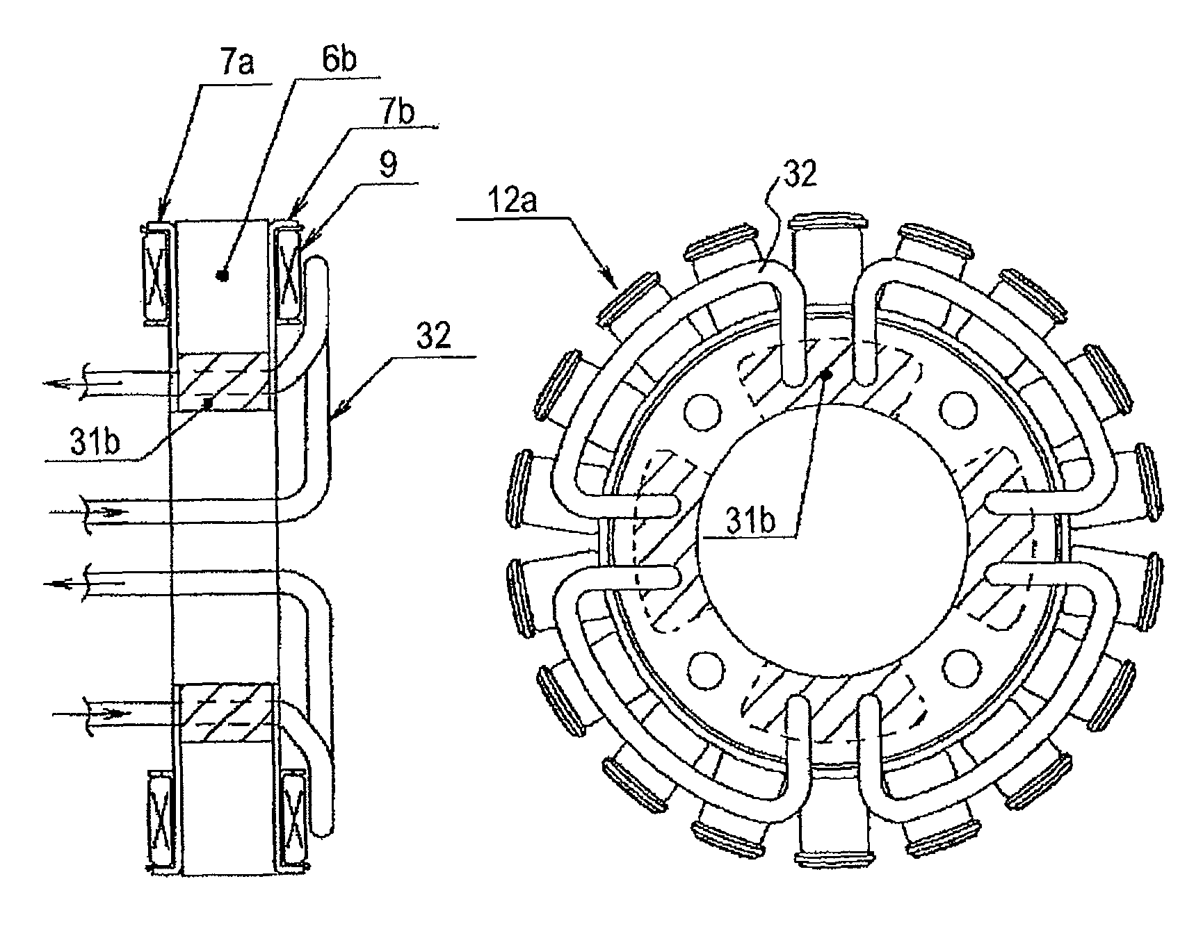
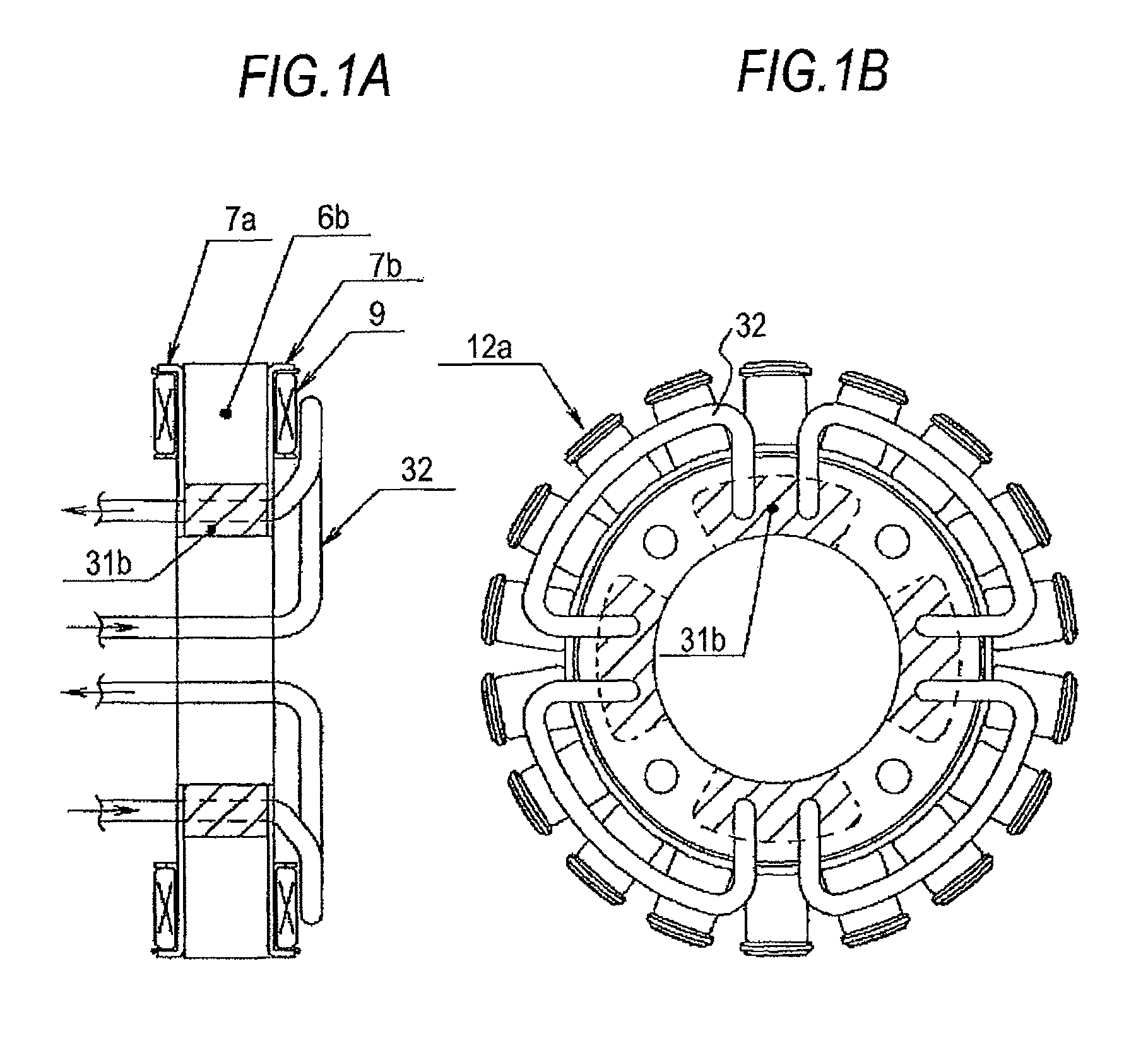
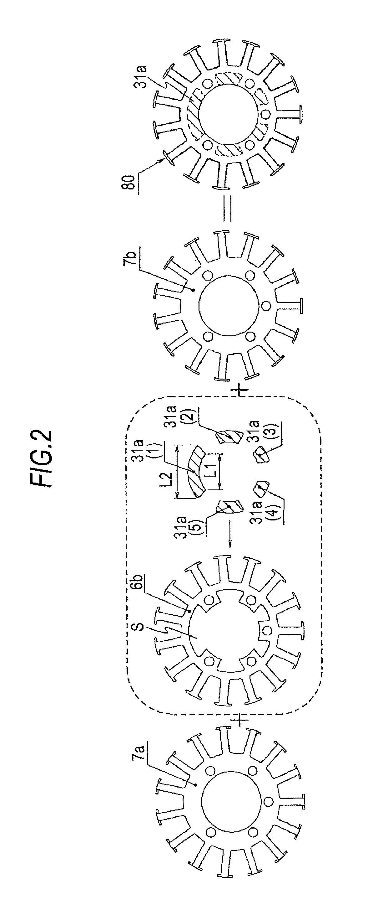
[0039]FIGS. 1A and 1B illustrate a stator part of a magnet generator according to a first embodiment of the invention. FIG. 1A is a side cross-sectional view, and FIG. 1B is a plan cross-sectional view. In FIGS. 1A and 1B, reference numeral 12a denotes a stator of the magnet generator. As illustrated in FIG. 2 described later, a heat dissipation enhancing member (hereinafter, simply referred to as a heat dissipation member) 31b is fitted into a space formed by cutting a bulk of an iron core 6b (thin steel sheet) used for configuring a magnetic field circuit, and a cooling tube 32 is allowed to penetrate the laminated core which is configured by blocking both side surfaces thereof with single plates 7a and 7b and is then distributed freely in the vicinity of a winding coil 9, thereby enhancing heat dissipation performance and cooling performance of the laminated core itself of the stator and suppressing a temperature increase in the winding coil 9. In addition, the cooling tube 32 is...

second embodiment

[0049]FIGS. 5A and 5B illustrate a stator part of a magnet generator according to a second embodiment of the invention. FIG. 5A is a side cross-sectional view, and FIG. 5B is a plan cross-sectional view.

[0050]In the second embodiment of the invention illustrated in FIGS. 5A and 5B, a stator 12b of the magnet generator is illustrated in a case where a clearance between the winding coil 9 and an inner side of a bottom part of the flywheel (not shown) is insufficient and the cooling tube cannot be distributed on the winding coil 9 side.

[0051]In the second embodiment, the configuration of the laminated core is the same as that in the first embodiment. However, unlike the heat dissipation member 31b of the first embodiment in which a through-hole is provided in the heat dissipation member to distribute the cooling tube to the vicinity of the winding coil 9, by a cooling tube 33 folded (or inserted inside the heat dissipation member 31c) inside the heat dissipation member 31c as the block...

third embodiment

[0052]FIGS. 6A to 9B illustrate a stator part of a magnet generator according to a third embodiment of the invention. FIGS. 6A, 7A, 8A, and 9A are side cross-sectional views, and FIGS. 6B, 7B, 8B, and 9B are plan cross-sectional views.

[0053]In the third embodiment of the invention illustrated in FIGS. 6A to 9B, a case where a cooling tube cannot be installed due to a configuration of an engine or due to a layout is illustrated.

[0054]FIGS. 6A and 6B illustrate a magnet generator which is mounted to an internal combustion engine shaft 101 by a flange bolt 102, and in the magnet generator illustrated in FIGS. 5A and 5B, a stator 11a according to the invention is fastened and fixed to the existing engine case cover (engine block) 201 which is not provided with a cooling medium passage, by a mounting bolt 103. In the stator 11a, only a heat dissipation member 31A such as an aluminum member is interposed between end plates of the laminated core. In a case where it is difficult for a cooli...


PUM


Abstract

In a flywheel-type magnet generator, a heat dissipation member which has no relation with a magnetic circuit is fitted into a space formed by cutting a bulk of a laminated core used for configuring the magnetic circuit, a cooling tube installed to be inserted into or penetrate the heat dissipation member is provided, and by supplying a cooling medium to the cooling tube, cooling performance of the stator is enhanced.

Description

BACKGROUND OF THE INVENTION[0001]1. Field of the Invention[0002]The present invention relates to a magnet generator for generating power by an electromagnetic induction between a magnet and an armature winding due to rotation of a flywheel.[0003]2. Description of the Related Art[0004]FIGS. 16A, 16B, 17 and 18 illustrate an example of an existing flywheel-type magnet generator. FIG. 16A is a side cross-sectional view, FIG. 16B is a plan cross-sectional view, FIG. 17 is a diagram illustrating a state where a laminated core of the magnet generator is fastened (mounted) to a rotation shaft of an internal combustion engine shaft or the like using a flange bolt, and FIG. 18 illustrates an example of the existing laminated core.[0005]In FIGS. 16A, 16B, 17, and 18, reference numeral 1 denotes a flywheel which is a rotor forming a bowl-shaped contour and including a vent 1a and a boss 1b to be fitted to the internal combustion engine shaft or the like. Reference numeral 2 denotes a plurality...

Claims


Application Information

Patent Timeline
Patent Type & Authority Patents(United States)
IPC IPC(8): H02K9/00
CPCH02K1/20H02K3/24H02K9/005H02K9/19H02K21/222H02K9/00H02K9/197
Inventor HASHIBA, MITSUHARU
Owner MITSUBISHI ELECTRIC CORP
Why Eureka
Try Eureka