LDPC design for high parallelism, low error floor, and simple encoding

a high parallelism, low error floor technology, applied in the field of communication and data storage systems, can solve the problems of large accumulation, high error floor, and difficult to achieve performance targets of some coding systems, and achieve high error floor, simple encoding, and good code performance.

Active Publication Date: 2014-08-14
QUALCOMM INC
View PDF8 Cites 43 Cited by
  • Summary
  • Abstract
  • Description
  • Claims
  • Application Information

AI Technical Summary

Benefits of technology

The patent text discusses a difficulty in using accumulate structures in LDPC code designs to support high performance targets with very low error rates. Large accumulate structures can lead to high error floors, which negatively impact performance. The text proposes a way to modify accumulate structures while retaining simplicity in the encoding process. The proposed solution involves increasing the degree of certain variable nodes in the accumulate chain or graph. This can be done by interpreting the LDPC code design as a ring of polynomials modulo a certain size. The text also mentions that matrices used in the encoding process are nearly triangular, with non-zero entries mostly on the diagonal and sub-diagonal. Increasing the degree of certain variable nodes can improve performance. However, this can complicate the encoding process.

Problems solved by technology

In coding systems that target very low error rates, however, large accumulate structures can be problematic in that they lead to high error floors.
The performance targets for some coding systems are therefore difficult to achieve with cyclic lifted designs that use an accumulate structure.
Doing so, however, generally complicates the encoding process.
In coding systems that target very low error rates, however, large accumulate structures can be problematic in that they lead to high error floors.
Doing so, however, generally complicates the encoding process.

Method used


Image

  • LDPC design for high parallelism, low error floor, and simple encoding
  • LDPC design for high parallelism, low error floor, and simple encoding
  • LDPC design for high parallelism, low error floor, and simple encoding

Examples


Embodiment Construction

[0025]In the following description, numerous specific details are set forth such as examples of specific components, circuits, and processes to provide a thorough understanding of the present disclosure. The term “coupled” as used herein means connected directly to or connected through one or more intervening components or circuits. Also, in the following description and for purposes of explanation, specific nomenclature is set forth to provide a thorough understanding of the present embodiments. However, it will be apparent to one skilled in the art that these specific details may not be required to practice the present embodiments. In other instances, well-known circuits and devices are shown in block diagram form to avoid obscuring the present disclosure. Any of the signals provided over various buses described herein may be time-multiplexed with other signals and provided over one or more common buses. Additionally, the interconnection between circuit elements or software blocks...


PUM


Abstract

A method of data encoding is disclosed. An encoder receives a set of information bits and performs an LDPC encoding operation on the set of information bits to produce a codeword based on a matched lifted LDPC code. The matched lifted LDPC code is based on a commutative lifting group and includes a number of parity bits and a submatrix to determine values of the parity bits. An order of the lifting group (Z) corresponds with a size of the lifting. A determinant of the submatrix is a polynomial of the form: ga+(g0+gL)P, where g0 is the identity element of the group, g0=gL2<sup2>k< / sup2>, and P is an arbitrary non-zero element of a binary group ring associated to the lifting group.

Description

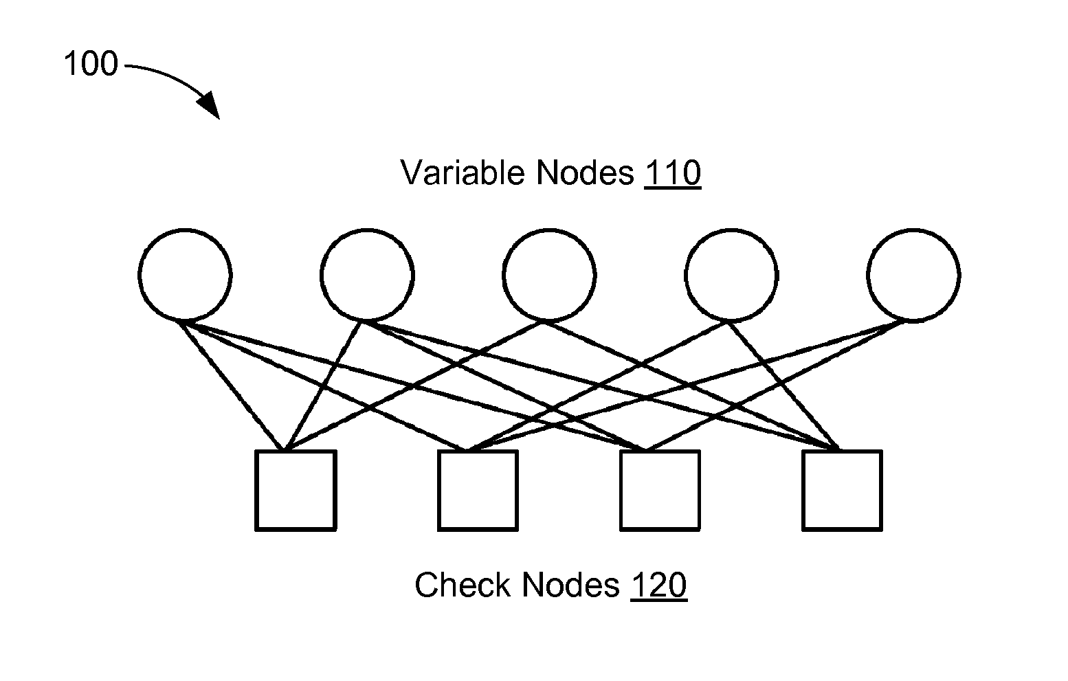
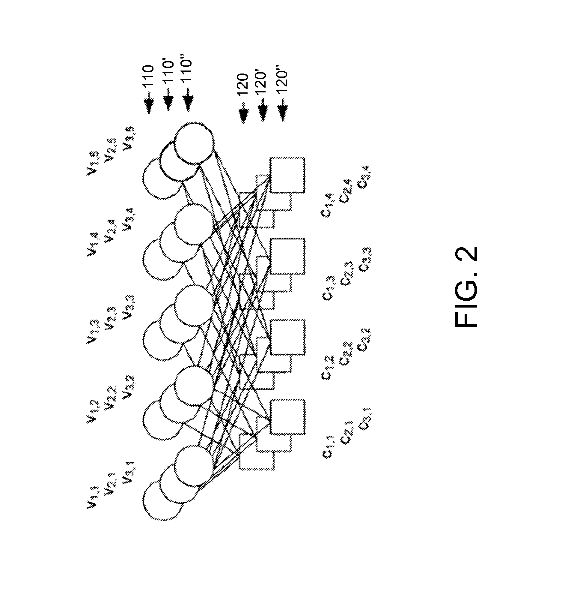
RELATED APPLICATIONS[0001]This application claims priority under 35 U.S.C. §119(e) of the co-pending and commonly-owned U.S. Provisional Patent Application No. 61 / 764,476, titled “LDPC Design for High Rate, High Parallelism, Low Error Floor, and Simple Encoding,” filed Feb. 13, 2013, which is hereby incorporated by reference in its entirety.TECHNICAL FIELD[0002]The present embodiments relate generally to communications and data storage systems, and specifically to communications and data storage systems that use LDPC codes.BACKGROUND OF RELATED ART[0003]Many communications systems use error-correcting codes. Specifically, error correcting codes compensate for the intrinsic unreliability of information transfer in these systems by introducing redundancy into the data stream. Low density parity check (LDPC) codes are a particular type of error correcting codes which use an iterative coding system. LDPC codes can be represented by bipartite graphs (often referred to as “Tanner graphs”)...

Claims


Application Information

Patent Timeline
IPC IPC(8): H03M13/11
CPCH03M13/118H03M13/036H03M13/1137H03M13/116H03M13/1168H03M13/1185H03M13/1188H03M13/611H03M13/6362H03M13/1105
Inventor RICHARDSON, THOMAS JOSEPH
Owner QUALCOMM INC
Why Eureka
Try Eureka