
Enhanced Backup Ring Edge Features for Metal Face Seal in Roller Cone Drill Bits

a technology of roller cone drill bits and edge features, which is applied in the direction of engine seals, mechanical equipment, construction, etc., can solve the problems of sealing failure, material deformation, loss of function, and typical failure, so as to increase the hardness of the material, increase the edge density, and increase the force

Inactive Publication Date: 2014-08-14
BAKER HUGHES INC
View PDF5 Cites 3 Cited by
  • Summary
  • Abstract
  • Description
  • Claims
  • Application Information

AI Technical Summary

Benefits of technology

The patent is about a way to make a backup ring for a face seal in a roller cone bit that is more resistant to wear from drilling fluids. The method involves removing material from the exposed end face in a specific pattern and increasing the hardness of the material. This helps to offset the force that would be transmitted through the backup ring on the face seal assembly due to flexing. The removed material can be replaced with a spring. The method can also involve increasing the edge density of all or part of the exposed edges by using electron beam radiation or other techniques to make the edge region more durable. Other material removal patterns, such as a honeycomb structure, can also be used to optimize the design criteria for durability within a desired range of sealing and component contact force.

Problems solved by technology

Failure is typically in the form of tearing and wear generally initiating in the area of the outside diameter of the backup ring and on the surface engaged with one of the hard material seal components.
Field experience shows that this material can degrade and often suffers tear and loses its function.
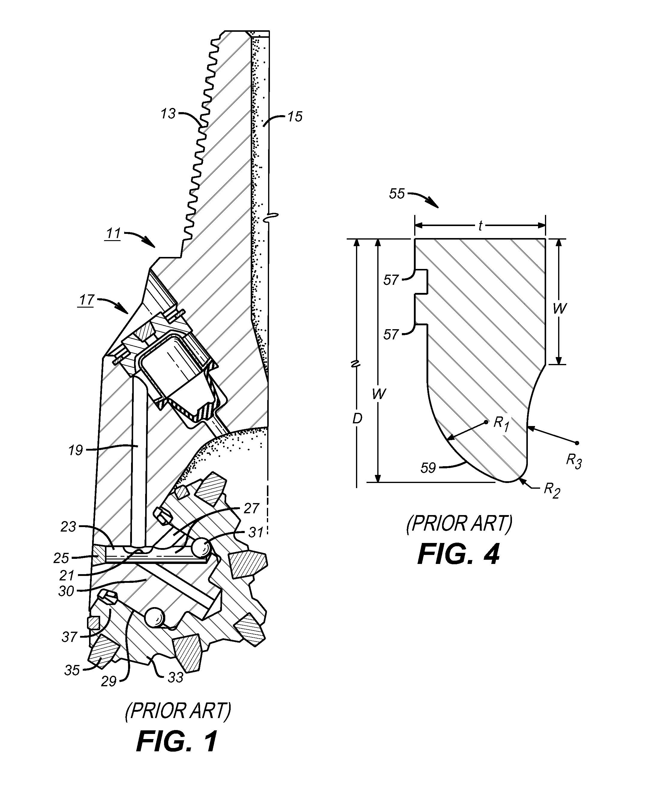
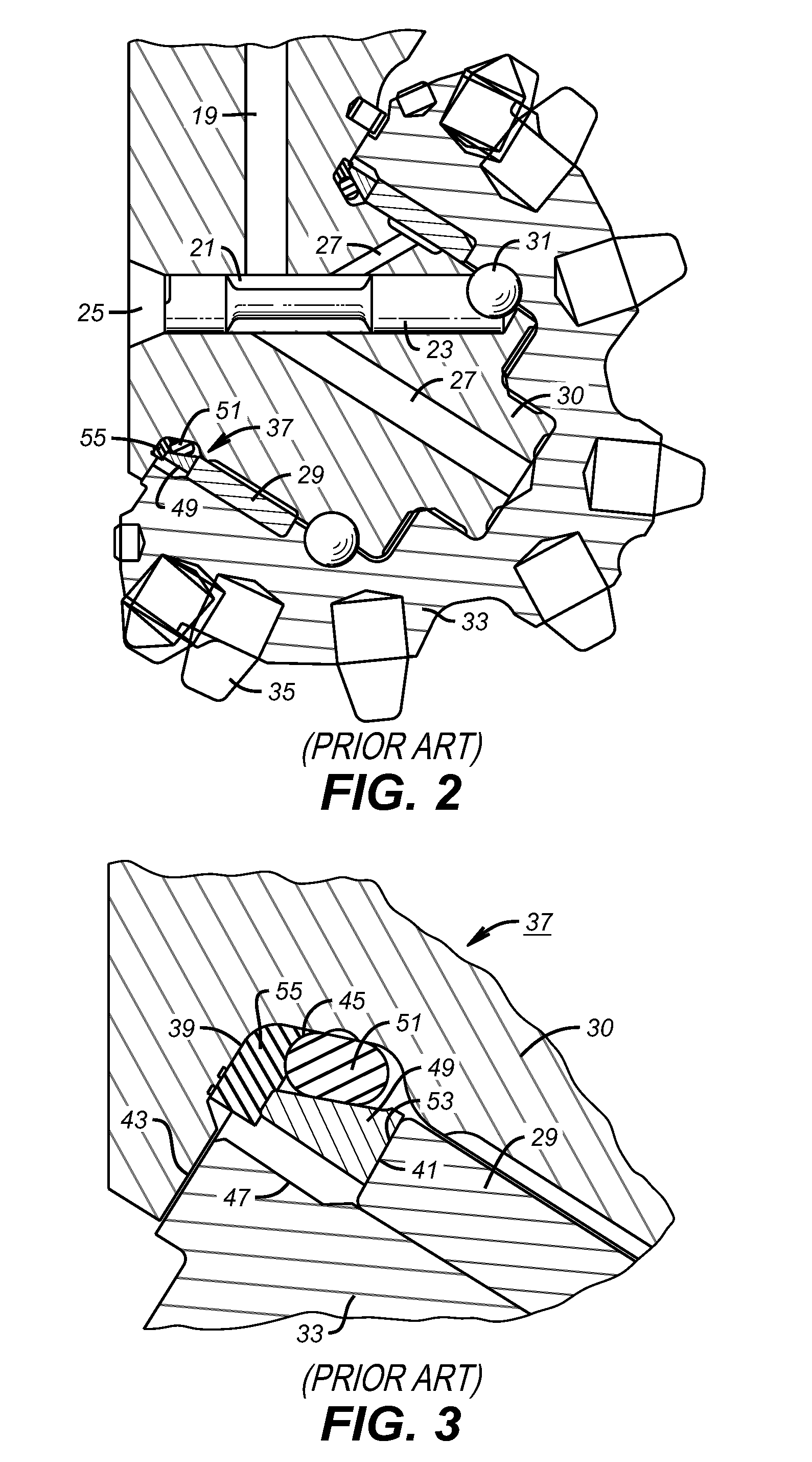
The problem with this design in the past is the tearing or breaking off of segments from the outer end of the backup ring 55 on the exposed face opposite surface 47 due to grit in the mud permeating toward this exposed surface that ultimately lead to seal failure of seal 37.

Method used


Image

  • Enhanced Backup Ring Edge Features for Metal Face Seal in Roller Cone Drill Bits
  • Enhanced Backup Ring Edge Features for Metal Face Seal in Roller Cone Drill Bits
  • Enhanced Backup Ring Edge Features for Metal Face Seal in Roller Cone Drill Bits

Examples


Embodiment Construction

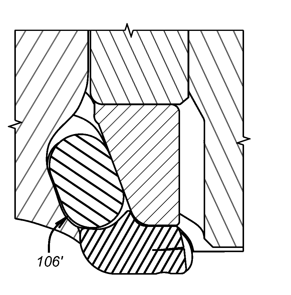
[0034]FIG. 5 shows the backup ring 100 of the present invention with an outer edge 102 that has a curved recess 104. When assembled to a roller cone face seal assembly 106 as previously described opposing forces 108 and 110 are represented by arrows. Assembly causes the recess 104 to get smaller than its relaxed uninstalled shape. The hardness of the ring 100 is increased as compared to the previously discussed prior embodiment where the hardness was 40-45 durometer (Shore A). The increase in hardness, modulus or density addresses the issue of cracking or pieces coming off from contact with the abrasives in well fluids notably drilling mud. However, the increase in hardness or density also increases the reaction forces to the forces represented by arrows 108 and 110. For that reason some material is removed from edge 102 that creates cantilevered components 112 and 114 that under loading from assembly and then during operation can flex toward each other to compensate for the increas...


PUM


Abstract

A backup ring for a face seal in a roller cone bit is configured to resist wear from drilling fluids present adjacent exposed faces of the backup ring. Portions are removed from an exposed end face in a variety of shapes while the hardness of the material is increased. The removal of material offsets an increase in force that would be transmitted through the backup ring on face seal assembly due to flexing. A spring can optionally be included in the removed material location. Another way is to increase the edge density of all or part of the exposed edges while leaving the interior portions unaffected by using electron beam radiation to increase the crosslink density or by other techniques that allow a unitary structure with a more durable edge region.

Description

FIELD OF THE INVENTION[0001]The field of the invention is roller cone drill bits and more particularly backup seal designs for face seals that increase durability while giving the desired contact pressure on the relatively moving components.BACKGROUND OF THE INVENTION[0002]Components of a rolling cone bit mechanical face seal system utilized to seal the bearing typically include (A) two hard material components typically metal having surfaces engaged and sliding with relation to each other, (B) an elastomeric static seal ring with the primary function of providing an energizing force to one of the hard material components such that the surfaces of the hard material components are engaged at some designed contact pressure, (C) a second static sealing elastomer component sometimes referred to as a backup ring residing outside of a first elastomer component and engaged with one of the hard material components. This second elastomer component having the primary function of stopping ingr...

Claims


Application Information

Patent Timeline
Patent Type & Authority Applications(United States)
IPC IPC(8): E21B10/25
CPCE21B10/25F16J15/344F16J15/328F16J15/3284
Inventor LIN, CHIHKOLTERMANN, TERRY J.ZAHRADNIK, ANTON F.RICKS, GREGORY L.
Owner BAKER HUGHES INC
Learn More