
Apparatus for separation and processing of materials

Active Publication Date: 2014-08-14
CYDAF TECH
View PDF3 Cites 21 Cited by
  • Summary
  • Abstract
  • Description
  • Claims
  • Application Information

AI Technical Summary

Benefits of technology

The patent describes a unit that can remove liquids or particles from a gas. It has the unique ability to separate out different fractions of the liquid. The design creates a smooth and uniform contact between the liquid and the rotating medium, allowing for complete layer insertion. Gas can also be inserted through the axially oriented stepped edges, creating a gas cushion that reduces friction. This design can be very effective for removing oil from oil-coated solids and enhancing many ore leaching applications.

Problems solved by technology

These variations result in local shear and eddies which in turn affect the particle separation efficiency.
Also, in the case of applications involving froth or dispersed air types of floatation, the froth and the particle-gas combinations are subject to considerable levels of destruction.
Obviously the orifice can be replaced with a different size of orifice but on-line adjustment is not available.
It must be remembered that the type of cyclonic separation device that is presented in this disclosure is not in general able to create such a thick and well dewatered underflow stream as can be achieved with a typical hydrocyclone unit.
This means that the centrifugal forces which act upon it as it rises up the centre of the core are generally not strong enough to clear all of the mid and oversize components out of it before it reaches the overhead outlet.
In these circumstances the quality of the overhead product can be affected not only by the gas inclusion but also by the poorer separation of the larger solids from the liquor which is routed to the overhead product from the last thickening stages of the underflow product.
These blockage issues would be particularly acute if the feed slurry contained heavy components (such as metal fragments), or inadequately screened oversize materials.
The principle draw back of this equipment is the limited ability of the separately created froth to maintain its function throughout the equipment.
However, it is anticipated that the degree of removal of the bituminous oil is not as high as it otherwise could be ifa) good particle on particle scraping were achieved and / orb) wash water or additional froth were provided towards the end of the separation process to sweep the residual fine bitumen particles out of the mother liquor which is incorporated with the sand fraction.

Method used


Image

  • Apparatus for separation and processing of materials
  • Apparatus for separation and processing of materials
  • Apparatus for separation and processing of materials

Examples


Embodiment Construction

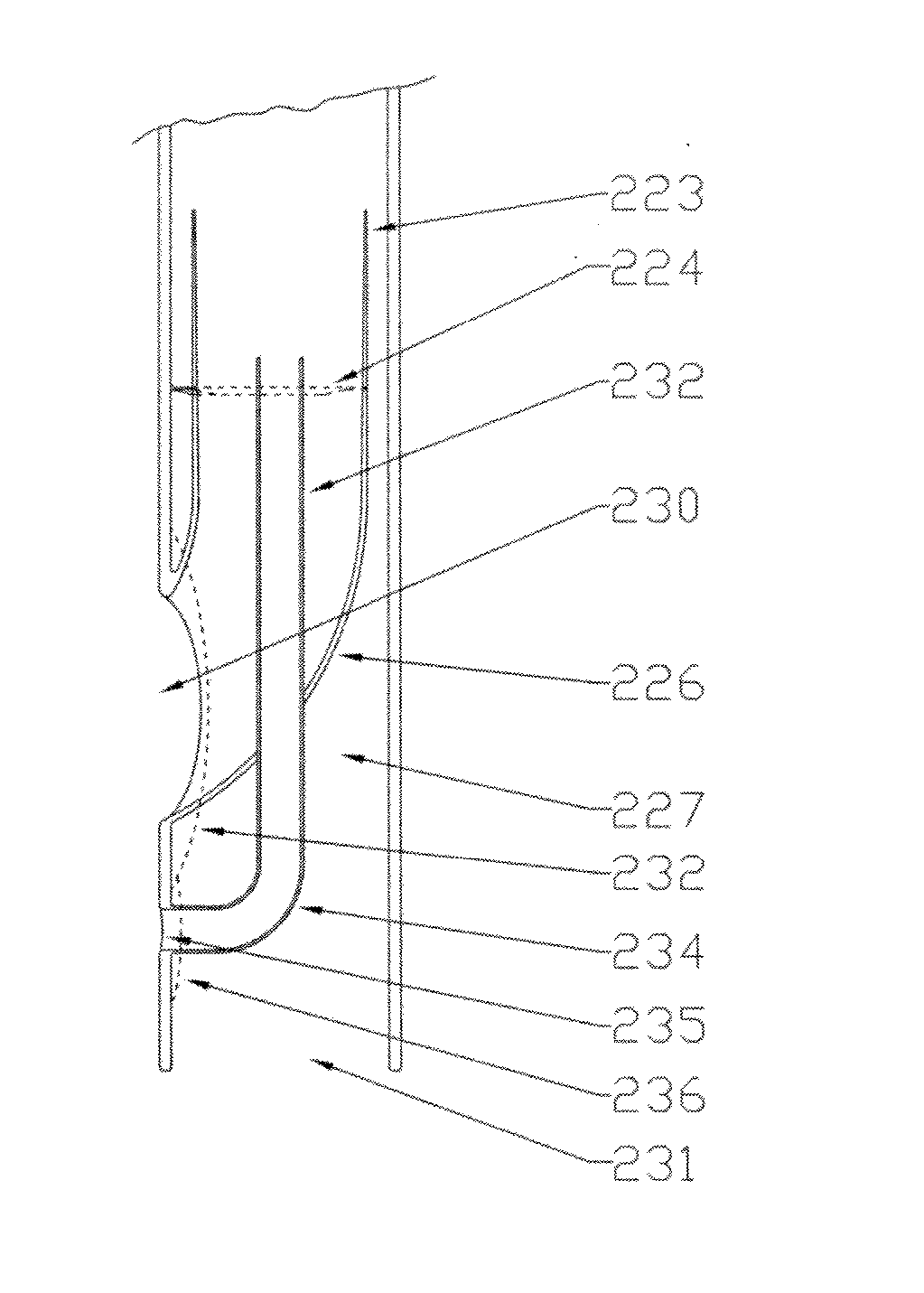
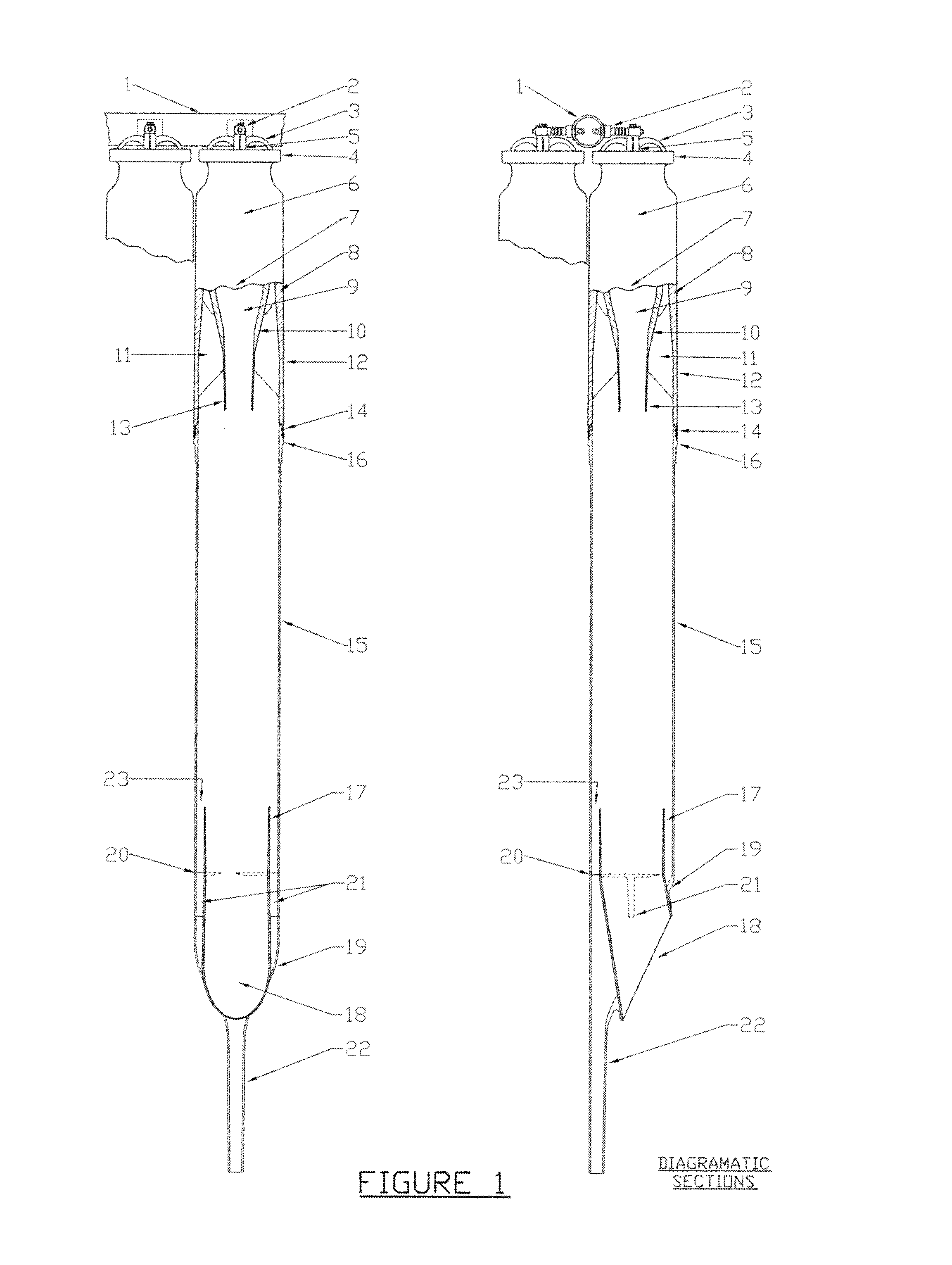
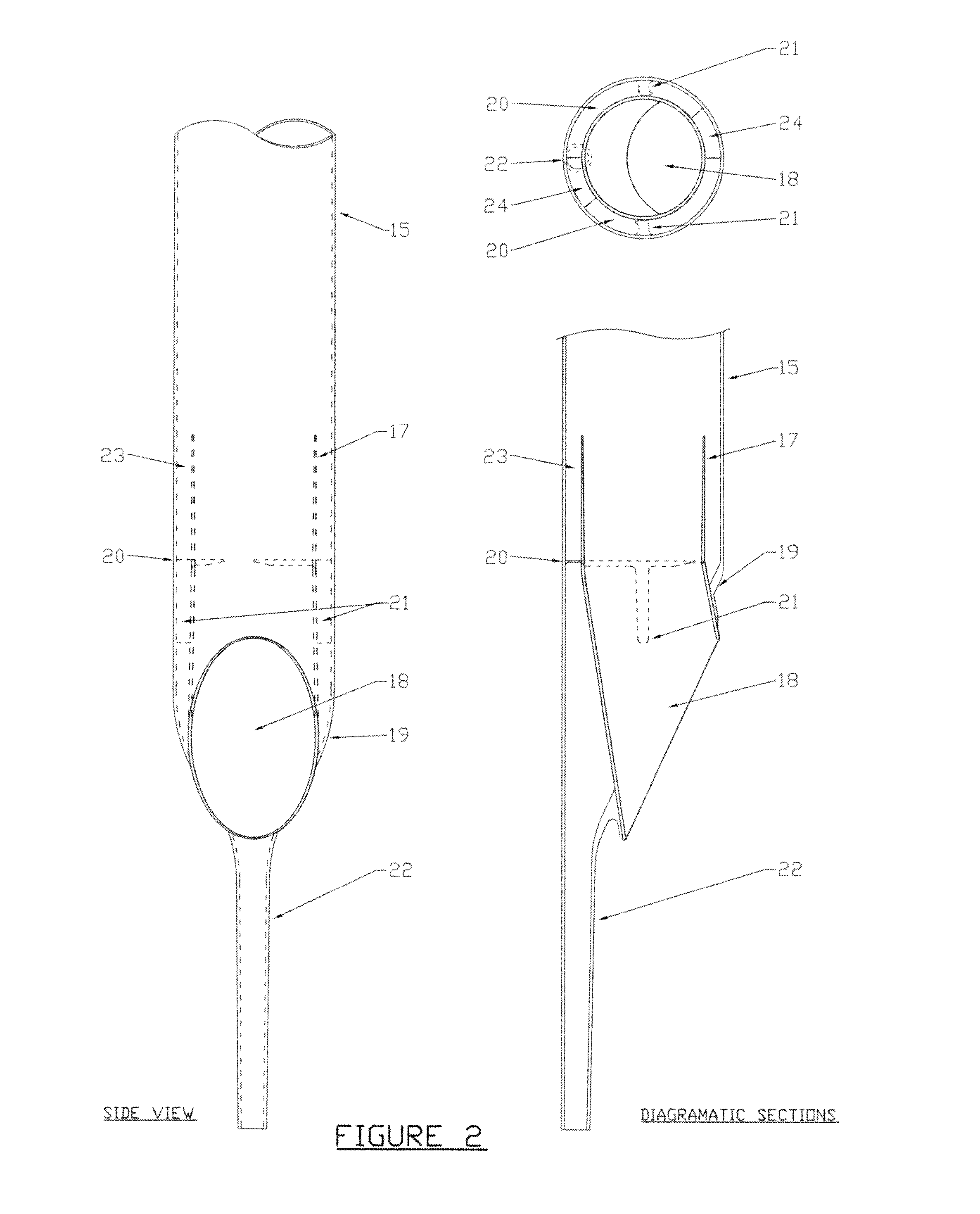
[0117]FIGS. 6A to 6D particularly focus on the “within the pipe” style of applications. FIGS. 7A and 7B together with FIGS. 8A to SC demonstrate how those same features and further features can be combined into the original design requirement. This requirement was for the unit to be entirely contained within the cylindrical profile of the cyclone tube itself no as to enable a number of such units to be mounted within a close packed arrangement within a carrier vessel.

[0118]It should be noted that none of these options require the units to be mounted vertically.

[0119]FIG. 7A shows how the simple two phase separation embodiment can be arranged so that it can be utilised as a number of parallel units in a close packed arrangement within a carrier vessel such as is shown in FIG. 9. By mounting the unit between two separating punch plates so as to create a three chamber carrier vessel, a very compact and high capacity system can be achieved.

[0120]Referring to FIG. 7A, it will be noted th...


PUM

PropertyMeasurementUnit
Fractionaaaaaaaaaa
Fractionaaaaaaaaaa
Angleaaaaaaaaaa

Abstract

This invention relates to a tubular cyclonic separation device the style of which was presented in PCT / ZA2003 / 000160 and which enables all of the inlet and outlet connections to be completely contained within a tubular profile, the diameter of which is that of the body of the cyclonic section. This disclosure adds further novel and inventive developments to the cyclonic device which enable it to be used as a separating device for systems involving all three phases (gas, liquid and solid) and where two, three or more different product streams may be separated, all within the same cylindrical profile. These further inventive developments also relate to the use of externally supplied gas and / or additional liquid phases which are injected through the walls of the cyclonic body using specifically located slots and / or holes in combination with specifically located stepped edges. These further novel and inventive developments enable the concepts of froth floatation (FF) and Dispersed Air Floatation (DAF) to be exploited within an enhanced gravitational field together with the options for washing the separated froth and / or the separated heavier fractions, all within the same cyclonic unit. As part of the novel and inventive introduction of the stepped edges, means are provided whereby gas bubbles smaller than 30 microns can be created on a large scale and with a reduced energy input relative to typical conventional equipment. Also the size of the gas bubbles may be controlled together with the intensity of any particle on particle interactions that may be created. This latter has many potential applications within FF and / or DAF processes, including applications within oil and tar separation from solid surfaces and within many ore preparation and ore leaching processes. The tubular profile enables processing and separation to be achieved “within the pipe line” or for very closely packed arrangements to be assembled within carrier vessels.

Description

FIELD OF INVENTION[0001]This invention relates to a tubular cyclonic separation device the basic form of which was presented in PCT / ZA2003 / 000160 with the primary purpose of separating a scrubbing liquor from a scrubbed gas stream as that gas stream exited a gas scrubbing device. The separation device was completely contained within a tubular profile, the diameter of which was that of the body of the cyclonic section itself. The gas-liquid mixture entered at an upper end of the device and the cleaned gas and the separated scrubbing liquor exited at the other lower end as separately ducted streams but all within the same cylindrical profile.[0002]Also, within this same disclosure was the use of a specifically profiled stepped edge within the gas scrubbing unit together with the creation and application of a highly abrasion resistant resin based system which could be either cast or moulded.[0003]This disclosure adds further novel and inventive developments to the cyclonic device which...

Claims


Application Information

Patent Timeline
IPC IPC(8): B01F3/04
CPCB04C5/28B04C5/13B01D17/0217B01D21/267B01D45/16B04C5/103B03D1/1418B04C5/06B01D21/2411B01D19/0057B04C5/14B01F3/0446B04C5/10B01D47/00B01F23/232
Inventor PAXTON, RICHARD, GEORGE
Owner CYDAF TECH
Learn More