
Dust removing device and imaging device

a technology which is applied in the field of dust removal device and imaging device, can solve the problems of unrealized zirconate titanate, lead-free piezoelectric material having various properties equivalent, and a large amount of lead, and achieves the effect of high dust removal performan

Active Publication Date: 2014-08-07
CANON KK
View PDF4 Cites 13 Cited by
  • Summary
  • Abstract
  • Description
  • Claims
  • Application Information

AI Technical Summary

Benefits of technology

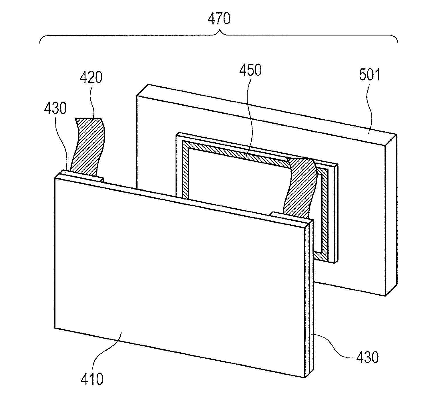
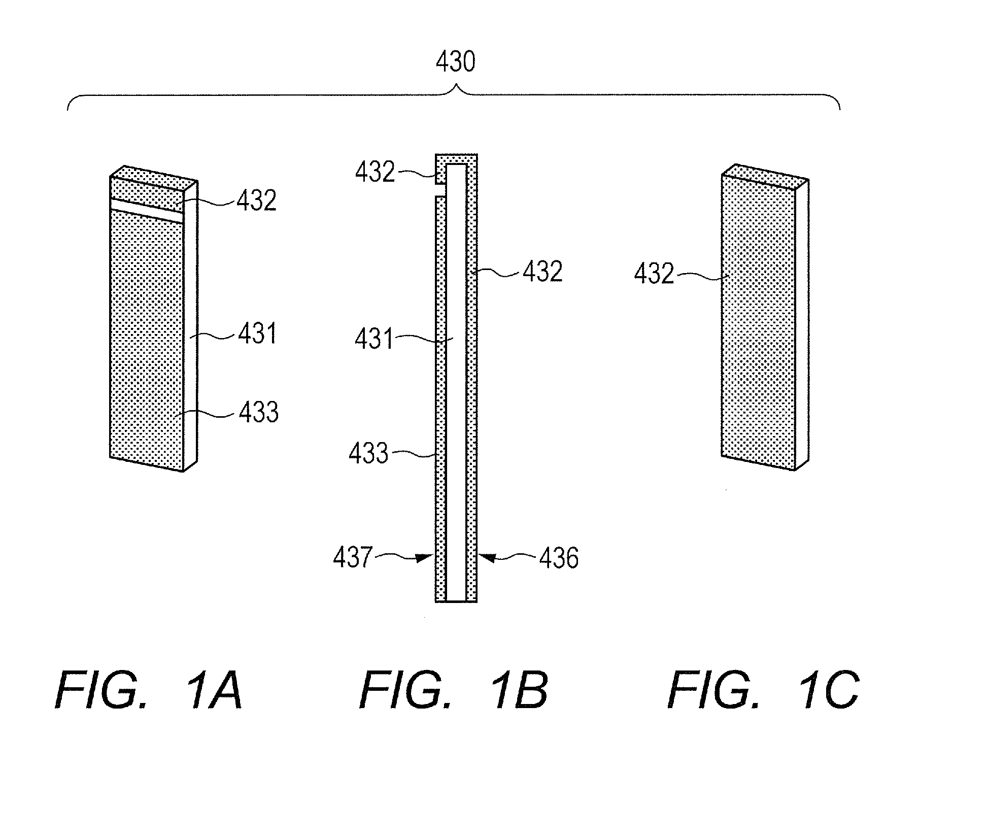
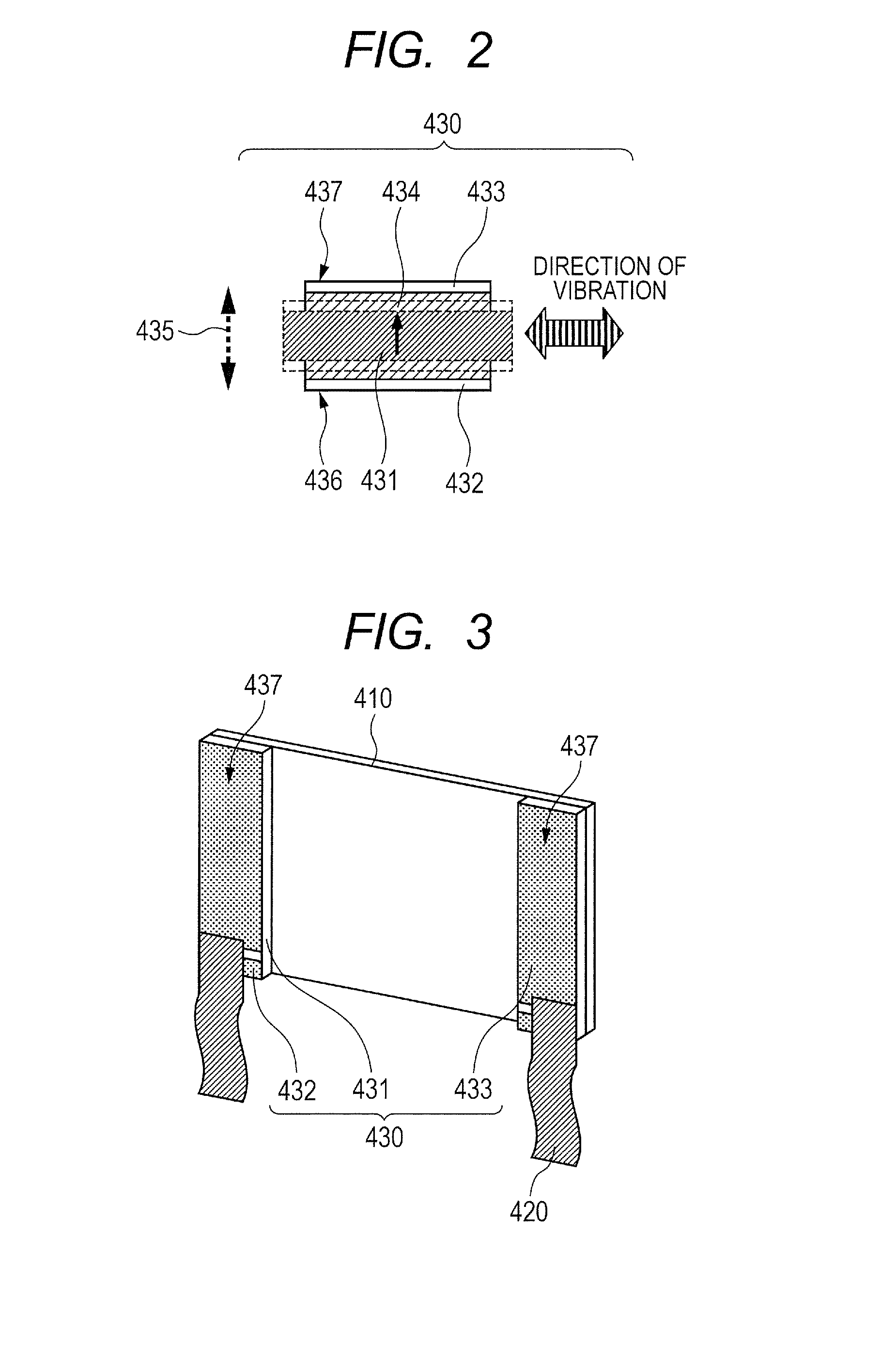
[0031]According to the present invention, a dust removing device capable of being designed and controlled appropriately and an imaging device using the dust removing device can be provided. Further, a dust removing device having high performance of removing dust even at low temperature and an imaging device using the dust removing device can be provided.
[0032]Further features of the present invention will become apparent from the following description of exemplary embodiments with reference to the attached drawings.

Problems solved by technology

In particular, in a single-lens reflex digital camera which includes an interchangeable lens, dust may enter the digital camera main body through the opening of the lens mount when the lens is being changed, and may adhere to the surfaces of the cover glass of the image pickup element or of the filters.
However, it has been pointed out that such a piezoelectric material made of lead zirconate titanate containing a large amount of lead can be detrimental to ecosystems because the lead component in the piezoelectric material seeps into soil when the piezoelectric material is once discarded to be exposed to acid rain, for example.
However, a prominent lead-free piezoelectric material having various properties equivalent to those of lead zirconate titanate has not been realized, and there are still only a few examples of commercialized devices using a lead-free piezoelectric material which is equivalent in quality to lead zirconate titanate.

Method used


Image

  • Dust removing device and imaging device
  • Dust removing device and imaging device
  • Dust removing device and imaging device

Examples


production example 1

[0185]Barium titanate (BT-01 produced by Sakai Chemical Industry Co., Ltd.) having an average particle diameter of 100 nm, calcium titanate (CT-03 produced by Sakai Chemical Industry Co., Ltd.) having an average particle diameter of 300 nm, and calcium zirconate (CZ-03 produced by Sakai Chemical Industry Co., Ltd.) having an average particle diameter of 300 nm were weighed in a molar ratio of 83.0:10.5:6.5.

[0186]Next, these weighed powders were mixed by dry blending for 24 hours through use of a ball mill. In order to granulate the mixed powder thus obtained, manganese acetate (II) whose Mn weight was to be 0.18 parts by weight on a metal basis with respect to the mixed powder and a PVA binder that was to be 3 parts by weight with respect to the mixed powder were respectively allowed to adhere to the surface of the mixed powder through use of a spray dryer.

[0187]Next, the granulated powder thus obtained was filled in a mold and supplied with a compacting pressure of 200 MPa through ...

production examples 2 to 27

[0207]Barium titanate (BT-01 produced by Sakai Chemical Industry Co., Ltd.) having an average particle diameter of 100 nm, calcium titanate (CT-03 produced by Sakai Chemical Industry Co., Ltd.) having an average particle diameter of 300 nm, and calcium zirconate (CZ-03 produced by Sakai Chemical Industry Co., Ltd.) having an average particle diameter of 300 nm were weighed to obtain a molar ratio shown in Table 1.

[0208]Next, these weighed powders were mixed by dry blending for 24 hours through use of a ball mill. In order to granulate the mixed powder thus obtained, manganese acetate (II) whose Mn weight was to be parts by weight shown in Table 1 on a metal basis with respect to the mixed powder and a PVA binder that was to be 3 parts by weight with respect to the mixed powder were respectively allowed to adhere to the surface of the mixed powder through use of a spray dryer.

[0209]Next, the granulated powder thus obtained was filled in a mold and supplied with a compacting pressure ...

examples 2 to 27

[0213]Piezoelectric elements of Examples 2 to 27 were produced using the piezoelectric materials of Production Examples 2 to 27.

[0214]Each piezoelectric material was polished to a thickness of 0.5 mm, and Ti and Au were formed to thicknesses of 30 nm and 380 nm respectively in this order on two surfaces of the material by DC magnetron sputtering to obtain a piezoelectric element having a first electrode and a second electrode.

[0215]Next, the piezoelectric elements were cut to dimensions of 10.0 mm×2.5 mm×0.5 mm, and thereafter, were polarized through use of a DC power source. A temperature was 100° C., an applied electric field was 1 kV / mm, and a voltage application time was 30 minutes. In this case, the polarization axis directions of the piezoelectric elements were parallel to a film thickness direction.

[0216]Further, a minute alternating electric field was applied to the piezoelectric elements of Examples 2 to 27 with varying measurement temperature to measure a dielectric consta...


PUM


Abstract

Provided is a dust removing device that can be designed and controlled appropriately and has high dust removal performance even at low temperature, and an imaging device using the dust removing device. In a dust removing device to be set on a base, including a piezoelectric element formed of a piezoelectric material and a pair of opposing electrodes, a vibration member, and a fixation member containing at least a high molecular compound component, a phase transition temperature T from a first ferroelectric crystal phase to a second ferroelectric crystal phase of the piezoelectric material is set to −60° C.≦T≦−5° C., and whereby, the dust removing device can be designed and controlled appropriately and high dust removal performance can be obtained even at low temperature.

Description

TECHNICAL FIELD[0001]The present invention relates to removing dust adhering to a surface of an imaging device such as a digital camera or a video camera and an optical component incorporated in the imaging device, and more particularly, to a dust removing device for removing dust through application of vibration.BACKGROUND ART[0002]In an imaging device such as a digital camera for picking up an image by converting an image signal into an electric signal, a photographing light flux is received by an image pickup element such as a charge coupled device (CCD) or a complementary metal oxide semiconductor (CMOS). Then, a photoelectric conversion signal output from the image pickup element is converted into image data, and the image data is recorded on a recording medium such as a memory card. In such an imaging device, an optical low-pass filter and an infrared cut filter are disposed in front (on a subject side) of the image pickup element.[0003]In the imaging device of this type, when...

Claims


Application Information

Patent Timeline
Patent Type & Authority Applications(United States)
IPC IPC(8): H02N2/00G02B27/00
CPCG02B27/0006H02N2/001B08B7/028H04N23/52H10N30/8536G03B2205/0061G03B2205/00B06B1/06B06B1/0607B08B7/02G02B27/00G03B17/00H10N30/85H04N23/811H04N25/60
Inventor IFUKU, TOSHIHIROSHIMIZU, YASUSHIFURUTA, TATSUOMATSUDA, TAKANORIKUBOTA, MAKOTOHAYASHI, JUMPEI
Owner CANON KK
Learn More