
Developing device and image forming apparatus

Inactive Publication Date: 2014-07-24
KONICA MINOLTA INC
View PDF3 Cites 4 Cited by
  • Summary
  • Abstract
  • Description
  • Claims
  • Application Information

AI Technical Summary

Benefits of technology

The present invention aims to provide a developing device and an image forming apparatus that can prevent the degradation of carriers, stabilize the electrical charge of developers, achieve a high transfer rate, prevent carrier adhesion, and produce high-quality images without fogging over a long period.

Problems solved by technology

This lowers the electrical chargeability of the carrier, i.e., lowers the ability to electrically charge the toner.
Thus, a repeated image formation impedes appropriate electrical charging of the toner, causing fogging and low image density of the images, which requires replacement of the developer after the formation of a certain number of images.
However, such a carrier inflicts a large amount of stress on a toner, accelerating the degradation of the carrier due to the spent toner problem.
This causes a decrease in an image quality due to fogging.
This may also cause a decrease in the transfer rate from the photoreceptor to a transfer medium and / or adhesion of the carrier.
If the amount of the carrier supplied is reduced, the image quality will decrease largely due to accelerated degradation of the carrier.
The copying of a document having a large black area consumes a large amount of toner.
As a result, a large amount of the developer is wasted.
Although an auto-refining development system is employed to extend the developer life and stabilize the image quality, the use of a developer containing a carrier having a large specific weight cannot sufficiently achieve these advantages over an extended period because a large amount of the developer is wasted.
Thus, a porous carrier having a small specific weight cannot sufficiently charge such a lowly charged toner within a short time.
This causes drawbacks such as fogging and toner scattering.

Method used


Image

  • Developing device and image forming apparatus
  • Developing device and image forming apparatus
  • Developing device and image forming apparatus

Examples


example

[0171]The present invention will now be described in detail with reference to Examples below. The present invention, however, is not limited to these examples.

(Preparation of Carrier Core Particle 1)

[0172]Raw materials were weighed to obtain 35 mol % MnO, 14.5 mol % MgO, 50 mol % Fe2O3 and 0.5 mol % SrO. The weighed raw materials were mixed with water and pulverized in a wet medium mill for five hours to obtain a slurry.

[0173]The obtained slurry was dried with a spray drier to obtain spherical particles. MnO was prepared from manganese carbonate, and MgO was prepared from magnesium hydroxide so as to adjust the poured bulk density. After the adjustment of the size of the particles, the particles were calcined for two hours at 950° C. A small poured bulk density and an appropriate fluidity were achieved by pulverization of the calcined particles in a wet ball mill for one hour with stainless steel beads having a diameter of 0.3 cm, followed by pulverization for four hours with zircon...


PUM


Abstract

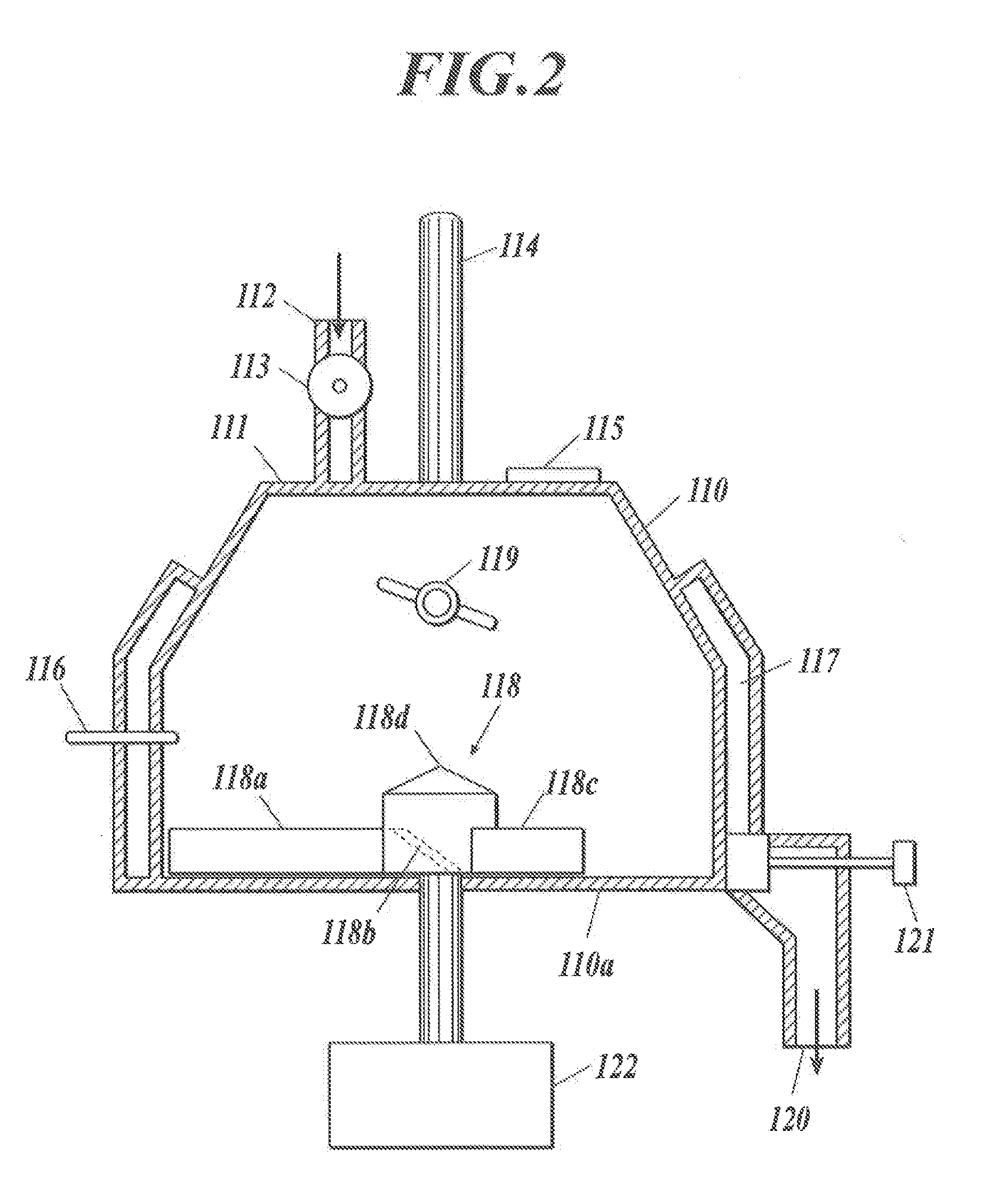
A developing device includes a developer container, a developing unit, a developer outlet and a replenishment developer inlet. The developer container contains a developer composed of a toner and a first carrier. The developing unit develops an electrostatic latent image on an image carrier using the developer. The developer outlet discharges the developer. The replenishment developer inlet supplies a replenishment developer to the developer container. The replenishment developer includes a second carrier. A ratio of a poured bulk density of the second carrier to a poured bulk density of the first carrier ranges from 0.60 to 0.95.

Description

BACKGROUND OF THE INVENTION[0001]1. Field of the Invention[0002]The present invention relates to a developing device and an image forming apparatus, and more specifically relates to an electrophotographic developing device that maintains a stable electrical charge for long-term use and stably provides high-quality images with high density and no fogging, and an electrophotographic image forming apparatus including the electrophotographic developing device.[0003]2. Description of Related Art[0004]In a typical electrophotographic image forming apparatus used in offices, a two-component developer is usually used. A two-component developer is used in a developing device in such a way that a toner and a carrier are agitated and mixed to electrically charge the toner and the charged toner is then provided on the surface of a photoreceptor to visualize (develop) an electrostatic latent image. Thus, only the toner is consumed in a repeated development of electrostatic latent images. The car...

Claims


Application Information

Patent Timeline
IPC IPC(8): G03G15/08G03G15/09
CPCG03G9/0833G03G9/0832G03G9/1075G03G9/1135G03G15/0879G03G2215/0607
Inventor NAKAMURA, KOSUKEKOZURU, HIROYUKIMATSUMOTO, YOSHIYASU
Owner KONICA MINOLTA INC
Learn More