
Method and apparatus for determining a relative orientation of points on a rigid body

Active Publication Date: 2014-07-17
PPG TECH
View PDF9 Cites 30 Cited by
  • Summary
  • Abstract
  • Description
  • Claims
  • Application Information

AI Technical Summary

Benefits of technology

The present disclosure discusses how to determine the orientation and distance between two points on a rigid body using an IMU and an accelerometer. The IMU includes a gyroscope and a first accelerometer, while the accelerometer measures acceleration. The controller in the IMU calculates the relative orientation and distance between the two sensors using the initial orientation calibration. This allows for accurate tracking of subsequent movements of the rigid body.

Problems solved by technology

However, an IMU is intrinsically unable to quantify the motion in terms of absolute position and orientation.
For example, in a case where an IMU is utilized to perform a swing analysis in golf, the IMU can report that the club face closed 2° over the course of the swing, but it cannot determine whether the face was closed or open at the start of the swing.
However, any deviation from this pre-defined position will cause corresponding inaccuracies in the results.
Similar methods rely on the golfer aligning the IMU device or / and the face normal to within a degree of some reference, which introduces user error.
Consequently, the accuracy of many output parameters is limited not by the IMU itself, but rather by the uncertainty in the club face orientation.
Consequently, inaccuracies are introduced by utilizing this technique.
These conditions are rarely met for the average golfer, which results in inaccurate swing analysis results.
Both these methods are quite susceptible to user error, and both assume the face normal was square with the target line at address, which is generally not true.

Method used


Image

  • Method and apparatus for determining a relative orientation of points on a rigid body
  • Method and apparatus for determining a relative orientation of points on a rigid body
  • Method and apparatus for determining a relative orientation of points on a rigid body

Examples


Embodiment Construction

[0029]Referring now to the drawings, wherein like reference numerals designate identical or corresponding parts throughout the several views.

[0030]For simplicity, the present disclosure discusses a golf club as an exemplary application for the method and device described herein; however, it should be appreciated that the present disclosure is not limited to golf, and the features described herein may easily be adapted by one of ordinary skill for use in performing initial orientation calibrations for other rigid bodies.

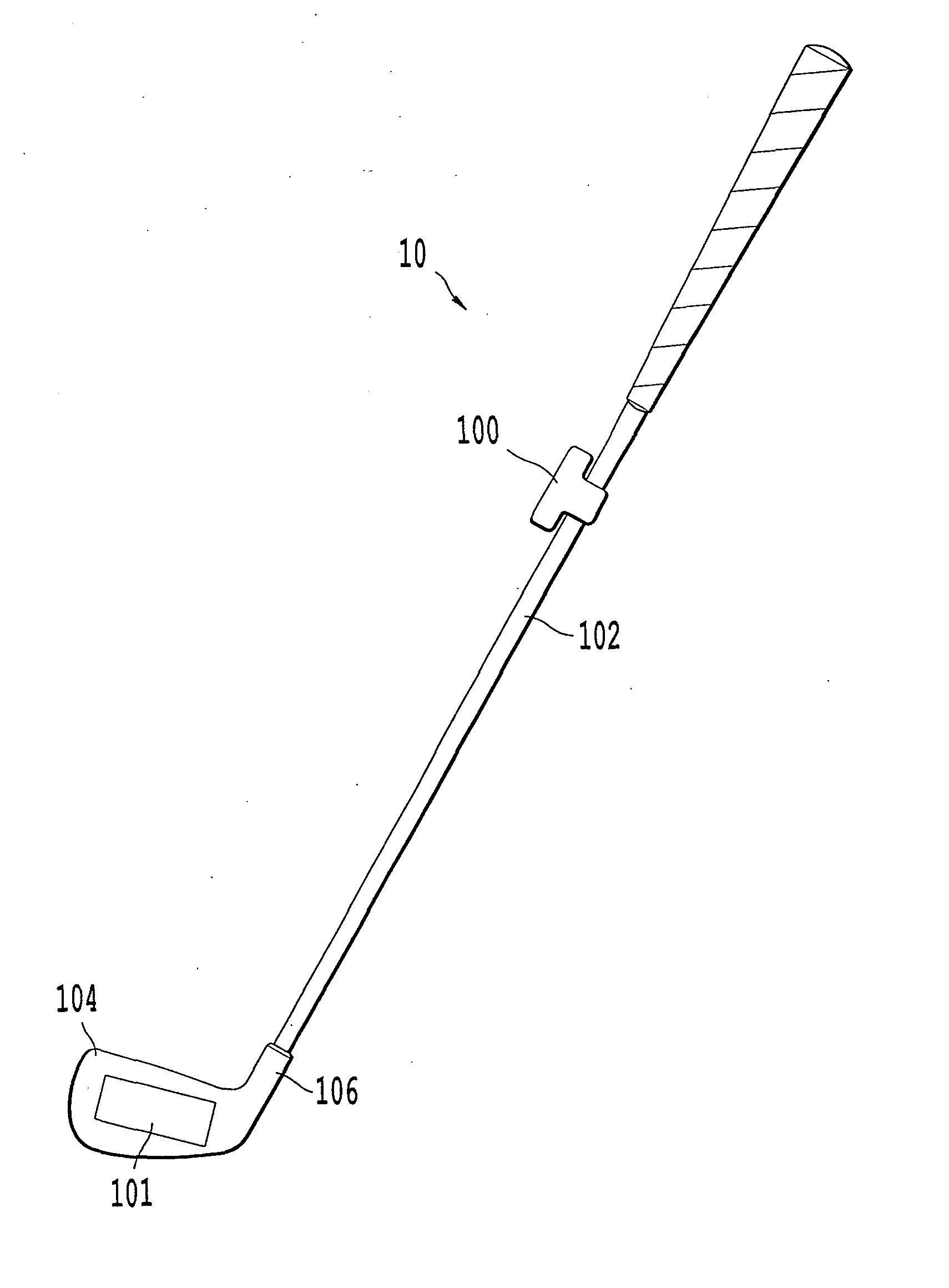
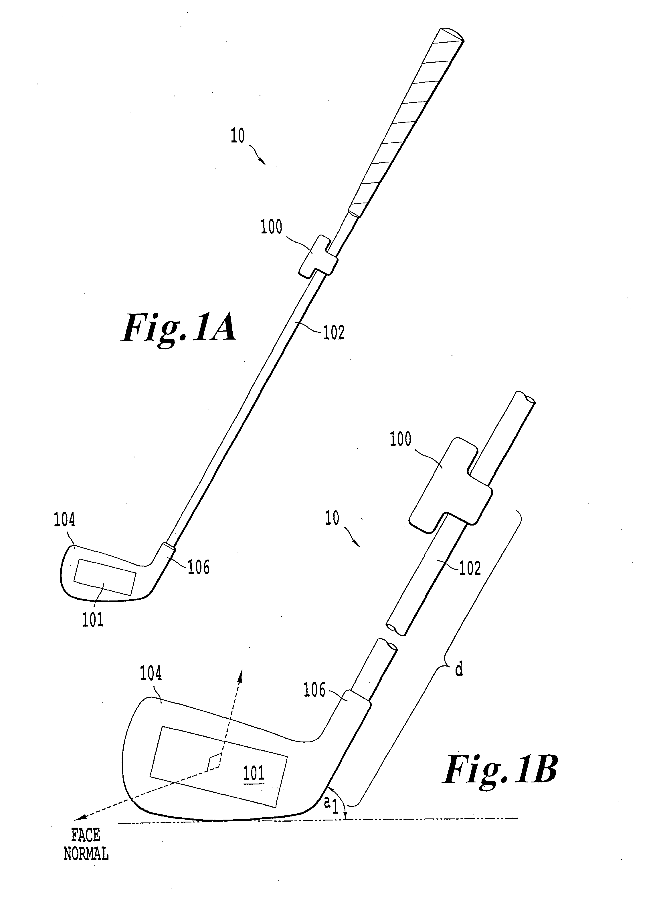
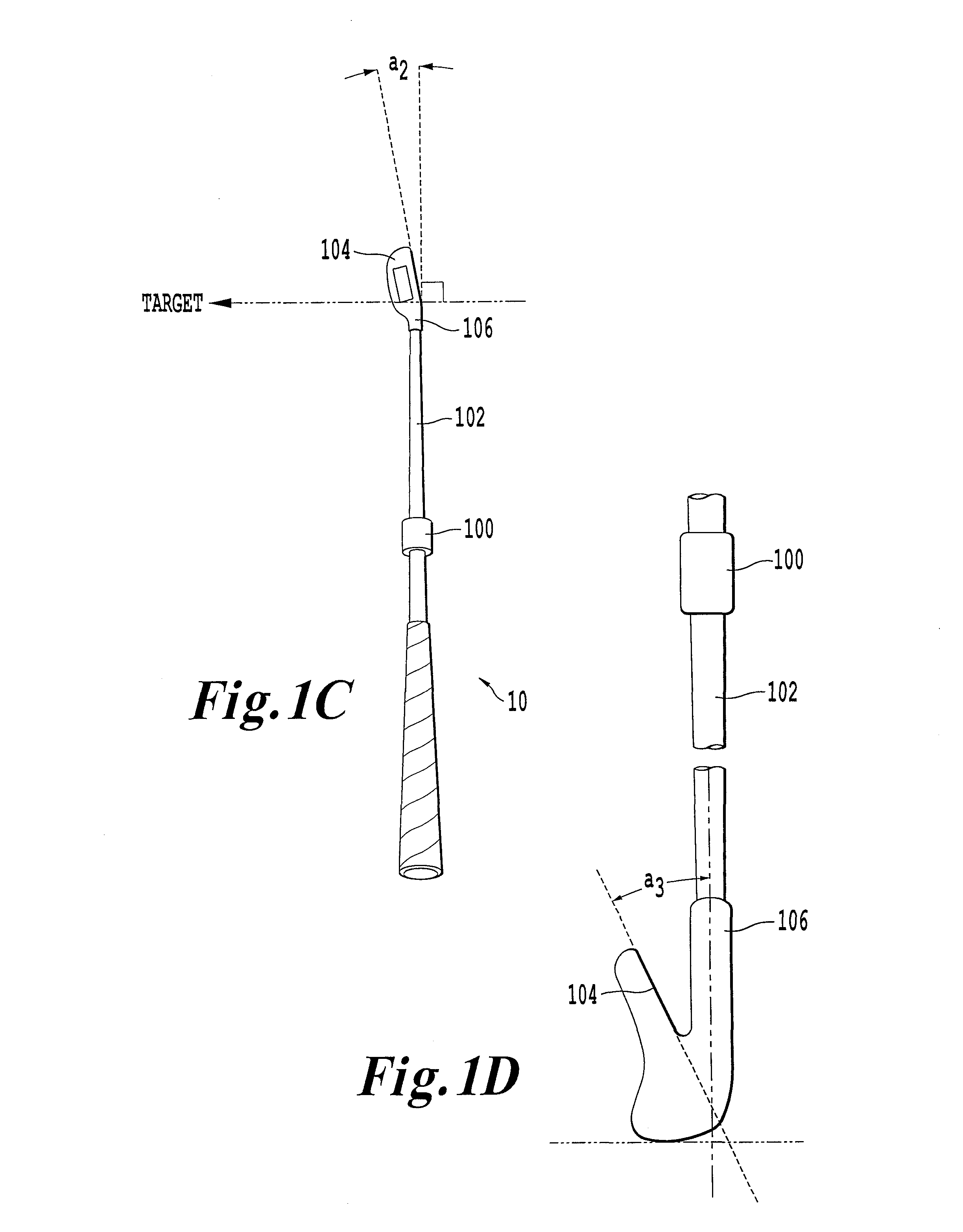
[0031]FIG. 1A illustrates an exemplary arrangement of IMUs for performing initial orientation calibration processing for a golf club. The arrangement of FIG. 1A includes a golf club 10, which includes a shaft IMU 100 and a face IMU 101 respectively attached to a shaft 102 and face 104, where the face 104 is the striking surface of club head 106. The shaft IMU 100 and the face IMU 101 are assumed to be functionally similar devices, and are numbered distinctly in the fi...


PUM


Abstract

An inertial measurement unit is affixed to a rigid body. The inertial measurement includes a gyroscope that measures a first angular velocity and an angular acceleration; a first accelerometer that measures a first acceleration; a communications unit that receives a measurement signal, the measurement signal including a second acceleration transmitted from a second accelerometer, the second accelerometer being affixed to the rigid body; and a controller that calculates a relative orientation of the inertial measurement unit and the second accelerometer, and a distance separating the inertial measurement unit and the second accelerometer.

Description

CROSS-REFERENCE TO RELATED APPLICATIONS[0001]This application relates to and incorporates by reference the disclosures of U.S. patent application Ser. No. ______ (attorney docket number 405887US105) and U.S. patent application Ser. No. ______ (attorney docket number 405893US105).BACKGROUND[0002]1. Field of the Disclosure[0003]The present disclosure relates to a device and method for performing an initial orientation calibration for an inertial measurement unit.[0004]2. Description of the Related Art[0005]An Inertial Measurement Unit (IMU) is an electronic sensor suite, generally comprised of accelerometers, gyroscopes, and magnetometers, which is used to measure the motion relative to an initial position and orientation. Among other things, IMUs are increasingly utilized to perform golf swing analysis, where the IMU measures the swing motion of a golf club relative to an initial position and orientation. However, an IMU is intrinsically unable to quantify the motion in terms of abso...

Claims


Application Information

Patent Timeline
IPC IPC(8): A63B69/36
CPCA63B69/3658G01P15/18G01C25/005G01P15/0888
Inventor PARKE, GORDONTSOURAS, ADAMMOUDAHI, EYTAN
Owner PPG TECH
Learn More