
Detecting gauge with high accuracy

Active Publication Date: 2014-07-17
SHENG KUO MACHINERY
View PDF6 Cites 5 Cited by
  • Summary
  • Abstract
  • Description
  • Claims
  • Application Information

AI Technical Summary

Benefits of technology

The invention provides a detecting gauge that ensures precise and smooth movement of the detecting apparatus. It helps to position the target in a stable manner for accurate detection, which simplifies the process and facilitates mass production.

Problems solved by technology

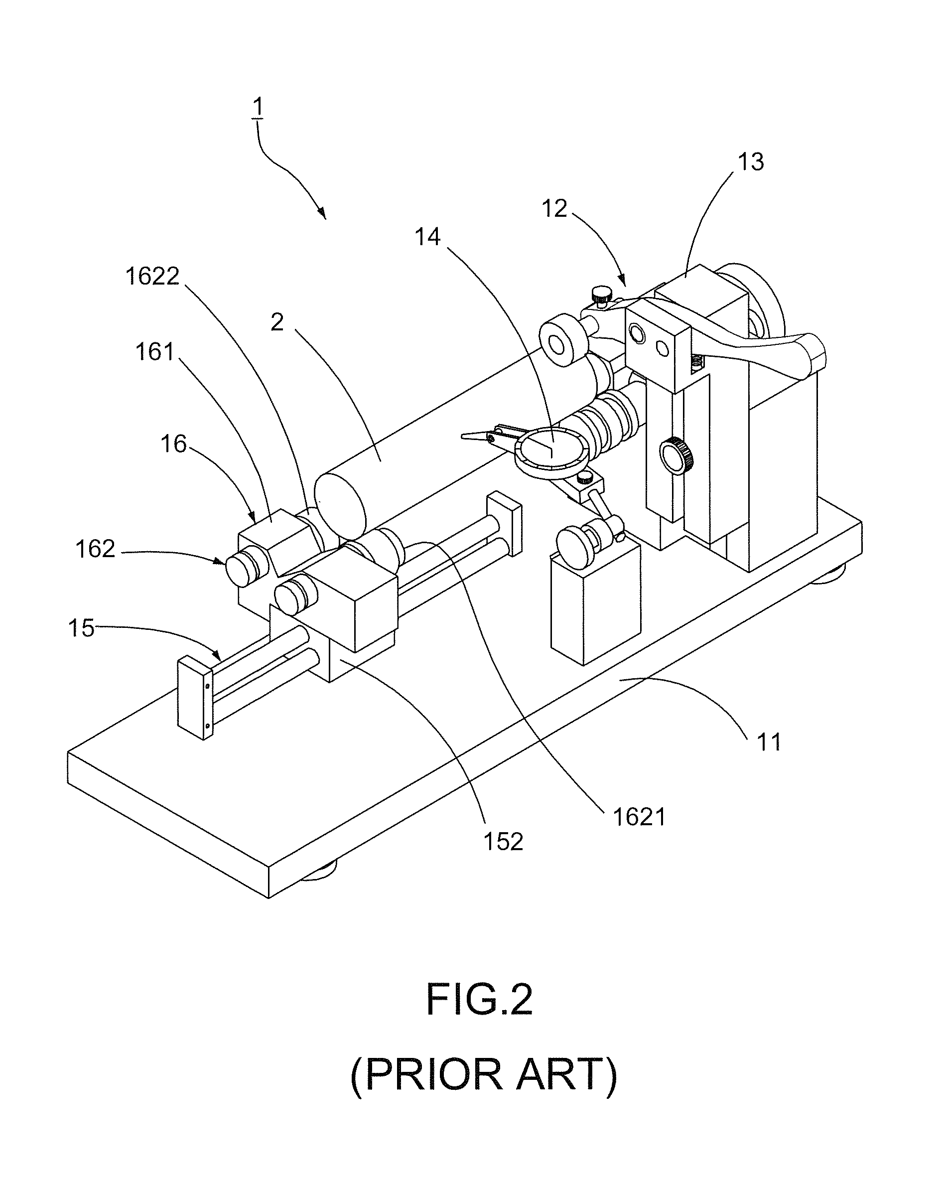
1. Generally, a plurality of rollers P shown in FIG. 3 are disposed inside the bearing 1622 of each supporting member 162, and a space S filled with lubricant (not shown) is usually retained in the interior of the bearing 1622 in advance for allowing the rollers P to rotate in the bearing 1622. However, while one end of the target 2 is placed on the bearings 1622 and the other end thereof is pressed by the clamping apparatus 13, the existence of the space S is apt to cause the deviation of the bearings 1622 by the weight of the target 2 itself and the pressing force of the clamping apparatus 13. Under the rotation of the bearings 1622, the target 2 will be deviated or inclined toward different direction by following the rotation. Therefore, the detected data measured by the detecting apparatus 14 becomes imprecise, and then the operator is apt to misjudge the detected data; that is, the operator sitting in judgment on whether the processing data of the target 2 is qualified is affected, which is however adverse to the following mass production.
2. Tolerance exists in most bearings 1622 while manufacturing, consequently, the factors that the bearing 1622 may still be loosely sleeved on the axle 1621 and the space S is retained in the interior of the bearing 1622 could have the adverse influence on the accuracy of measurement of the detecting apparatus 14.
3. Since the target 2 provides one end thereof merely griped by the clamping apparatus 13 and the other end thereof placed on the bearings 1622 by its weight, the longer the length of the target 2 is obtained, the easier the target 2 is affected by an exterior force or the rotation of the detecting procedure and deviated from the supporting apparatus 16 (as dotted line shown in FIG. 4). As a result, the detecting apparatus 14 cannot get the precise detected data of the target 2.

Method used


Image

  • Detecting gauge with high accuracy
  • Detecting gauge with high accuracy
  • Detecting gauge with high accuracy

Examples


first embodiment

[0038]Referring to FIG. 8, a second preferred embodiment of the detecting gauge 3 still comprises a machine table 31, a detecting set 32, a clamping apparatus 33, a detecting apparatus 34, and a sliding apparatus 35. The detailed components and the functions thereof are the same as the first embodiment and herein are omitted. Particularly, a supporting apparatus 36 is disposed on the sliding base 352 of the sliding apparatus 35. The supporting apparatus 36 includes a supporting base 361 disposed on the sliding base 352 and two supporting members 362 pivotally juxtaposed on the supporting base 361. The target 4 can be fitly placed across a middle of the axles 3312 and a middle of the supporting members 362. The detecting apparatus 34 can be disposed on one side of the machine table 31, and the position of the positioning unit 332 can be adjusted in accordance with the demand of use. For example, the base 3321 of the positioning unit 332 can be directly fixed on the driving unit 331 o...

second embodiment

[0041]Referring to FIG. 12 and FIG. 13, a forth preferred embodiment of the present invention still comprises the same components as the second embodiment and herein are omitted. Particularly, each supporting member 362 of the supporting apparatus 36 is an integrally-formed axle and does not need to be sleeved by any bearing. Therefore, the supporting members 362 will not have the existence of the space inside the bearing as disclosed in the conventional configuration. In this embodiment, the target 4 can be stably placed on the supporting members 362, and the deviation of the bearing caused by the press of the positioning apparatus 332 or the weight of the target 4 itself is prevented for making sure that the target 4 can be rotated without inclining or deviating, whereby the detecting apparatus 34 can exactly detect the specification of the target 4 to facilitate the following process and mass production.

[0042]To sum up, the detecting gauge with high accuracy mainly uses the slidi...


PUM


Abstract

A detecting gauge with high accuracy mainly comprises a machine table, a detecting set, a clamping apparatus, a detecting apparatus, and a sliding apparatus. Particularly, the sliding apparatus includes a sliding rail disposed on a machine table and a sliding base slidably disposed on said sliding rail. A sliding groove is disposed on both sides of the sliding rail, an embedding portion is formed on the sliding base for matching the sliding groove, and a plurality of rollers are embedded on a surface of said embedding portion which is in contact with said sliding groove. By matching the embedding portion with the sliding groove, the sliding base can be slid and moved precisely and smoothly on the sliding rail, and a target to be detected can be stably held by the clamping apparatus, whereby the detecting apparatus can obtain the measurement with high accuracy.

Description

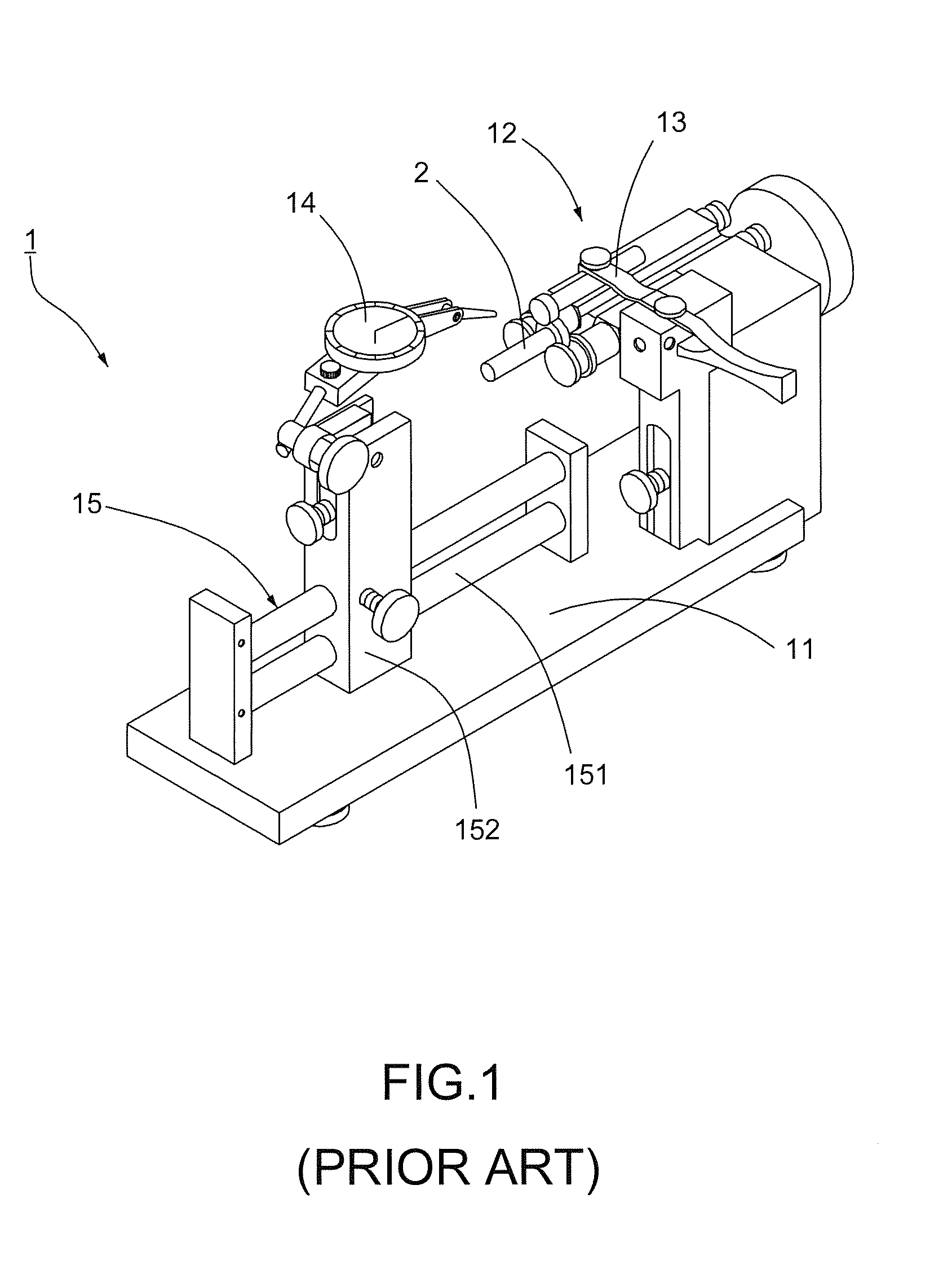
BACKGROUND OF THE INVENTION[0001]1. Field of the Invention[0002]The present invention relates to a detecting gauge, particularly to a detecting gauge with high accuracy.[0003]2. Description of the Related Art[0004]To ensure the quality of the following production, a procedure of detecting the pre-produced specifications must to be executed before a mass production of targets to be detected, such as screws, nuts, and nails. Generally, the targets are detected by a detecting gauge like a curvature instrument, a length instrument, and a concentric instrument.[0005]Referring to FIG. 1, a conventional detecting gauge 1 comprises a machine table 11 and a detecting set 12 disposed on the machine table 11; wherein the detecting gauge 1 is mainly used to detect a target 2 with a short length. The detecting set 12 includes a clamping apparatus 13 disposed on the machine table 11 and capable of clamping a target 2, a detecting apparatus 14 corresponding to the clamping apparatus 13, and a slid...

Claims


Application Information

Patent Timeline
IPC IPC(8): G01B5/00
CPCG01B5/00G01B5/0009
Inventor LIU, KUO-SHENG
Owner SHENG KUO MACHINERY
Learn More