
Dual relief valve of bsm for vehicle engine

a technology of bsm and vehicle engine, which is applied in the direction of valve operating means/release devices, machines/engines, etc., can solve the problems of fuel efficiency and output loss, high pressure oil discharged from the bsm may affect an oil filter or lubrication circuit, and may reduce the frictional resistance of the crank shaft. , to achieve the effect of minimizing the loss of the bsm, efficient control

Inactive Publication Date: 2014-07-03
HYUNDAI MOTOR CO LTD
View PDF5 Cites 3 Cited by
  • Summary
  • Abstract
  • Description
  • Claims
  • Application Information

AI Technical Summary

Benefits of technology

The present invention provides a dual relief valve for a BSM (oil supply system) in a vehicle engine that is composed of a primary and a secondary valve. This dual valve design allows for efficient control of oil discharge from the BSM in connection with low-speed, middle-low speed, and high-speed regions, reducing loss of the BSM and minimizing damage. This leads to improved fuel efficiency, reduced driving torque, and minimized output loss.

Problems solved by technology

For example, the lubrication places a great deal of weight on not only reduction in frictional resistance of a crank shaft, a connecting rod and a piston in the major moving part but also cooling of the piston and cylinder.
The oil discharged in a high-pressure state from the BSM may apply impact and damage to an oil filter or lubrication circuit.
However, in the BSM to which a conventional single-type relief valve is applied, fuel efficiency and output loss occur due to excessive driving torque.
Particularly, since the BSM uses a method in which the relief valve is simply opened or closed in response to the pressure of oil discharged therefrom, the amount of the oil discharged from the BSM is not properly controlled, and therefore, the BSM cannot effectively deal with various operation regions, thereby causing loss of the BSM.

Method used


Image

  • Dual relief valve of bsm for vehicle engine
  • Dual relief valve of bsm for vehicle engine
  • Dual relief valve of bsm for vehicle engine

Examples


Embodiment Construction

[0040]Hereinafter reference will now be made in detail to various embodiments of the present invention, examples of which are illustrated in the accompanying drawings and described below. While the invention will be described in conjunction with exemplary embodiments, it will be understood that present description is not intended to limit the invention to those exemplary embodiments. On the contrary, the invention is intended to cover not only the exemplary embodiments, but also various alternatives, modifications, equivalents and other embodiments, which may be included within the spirit and scope of the invention as defined by the appended claims.

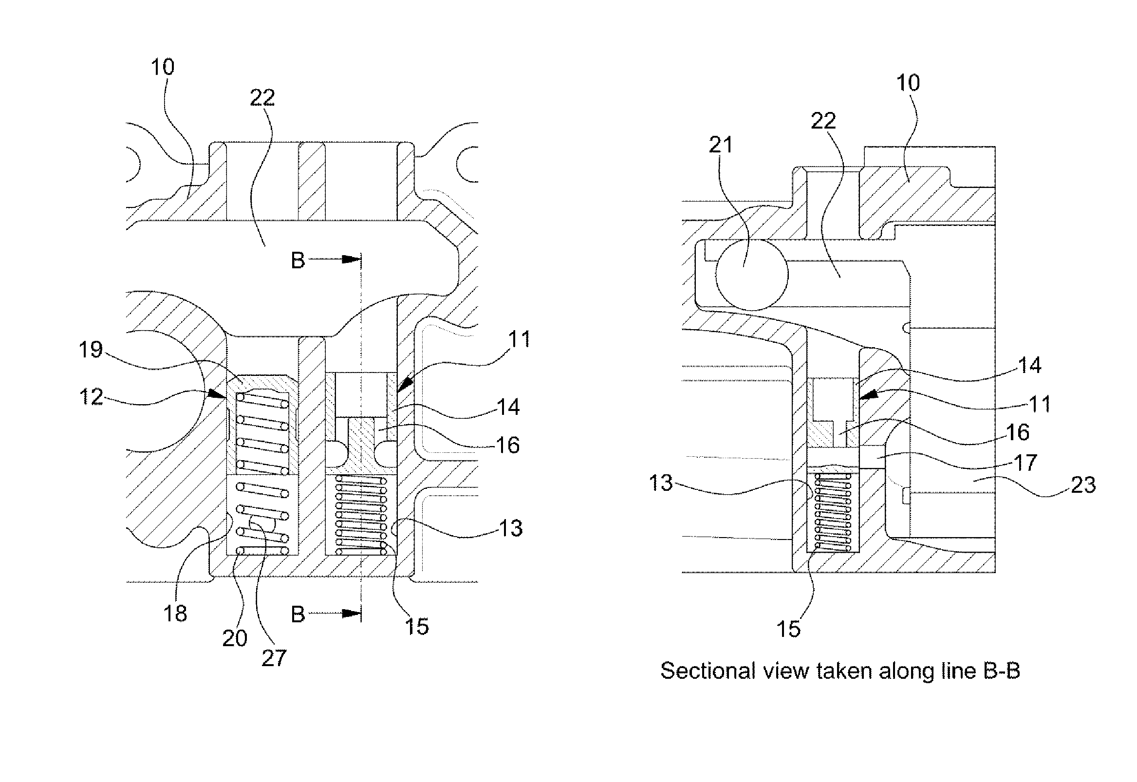
[0041]FIG. 3 is a sectional view showing a dual relief valve of a BSM according to an exemplary embodiment of the present invention.

[0042]As shown in FIG. 3, the dual relief valve of the BSM is configured with the combination of a primary relief valve releasing a primary oil at a low pressure and a secondary relief valve releasing a secon...


PUM


Abstract

A dual relief valve apparatus of a Balance Shaft and Oil Pump Module (BSM) of a vehicle engine may include the pump housing, and a primary relief valve and a secondary relief valve mounted inside the pump housing, wherein the primary relief valve and the secondary relief valve may be sequentially opened or closed, wherein the primary relief valve may be first opened to release a first oil by a first oil discharge pressure applied thereto and sequentially the secondary relief valve may be opened to release a second oil by a second oil discharge pressure applied thereto, the first oil discharge pressure being relatively smaller than the second oil discharge pressure.

Description

CROSS-REFERENCE TO RELATED APPLICATION[0001]The present application claims priority to Korean Patent Application No. 10-2012-0154213 filed Dec. 27, 2012, the entire contents of which is incorporated herein for all purposes by this reference.BACKGROUND OF THE INVENTION[0002]1. Field of the Invention[0003]The present invention relates to a dual relief valve of a BALANCE SHAFT & OIL PUMP MODULE (BSM) for a vehicle engine. More particularly, the present invention relates to a dual relief valve of a BSM for a vehicle engine, which can maintain the pressure of oil discharged from the BSM for the vehicle engine to be an appropriate pressure.[0004]2. Description of Related Art[0005]In general, the lubrication of a vehicle engine is very important to reduce frictional resistance inside the engine and to cool the inside of the engine.[0006]The lubrication of the vehicle engine is usually performed on all parts from a valve apparatus to a cylinder as well as a major moving part. For example, t...

Claims


Application Information

Patent Timeline
Patent Type & Authority Applications(United States)
IPC IPC(8): F04C14/24
CPCF04C14/24F04C2/18F04C2210/206F04C2270/185Y10T137/7794F16F15/267F16F15/00
Inventor SHIN, JEONG SOO
Owner HYUNDAI MOTOR CO LTD
Learn More