Receiver for a telecommunications system

a technology for telecommunications systems and receivers, applied in the field of telecommunications, can solve problems such as inability to use techniques, complex adc requirements with a large number of bits,

Inactive Publication Date: 2014-06-19
QUALCOMM TECH INT
View PDF1 Cites 6 Cited by
  • Summary
  • Abstract
  • Description
  • Claims
  • Application Information

AI Technical Summary

Benefits of technology

The present invention provides a near-field communication device and method for communicating with and powering a passive device using a clipped signal. The device includes an antenna and processing circuitry for demodulating the clipped signal. The technical effect is to improve the quality of near-field communication by using a clipped signal for better demodulation of data and power transmission.

Problems solved by technology

This can lead to a complex ADC requirement with a large number of bits.
With a bandpass ADC that digitises the 13.56 MHz input signal, however, this technique cannot be used.

Method used


Image

  • Receiver for a telecommunications system
  • Receiver for a telecommunications system
  • Receiver for a telecommunications system

Examples


Embodiment Construction

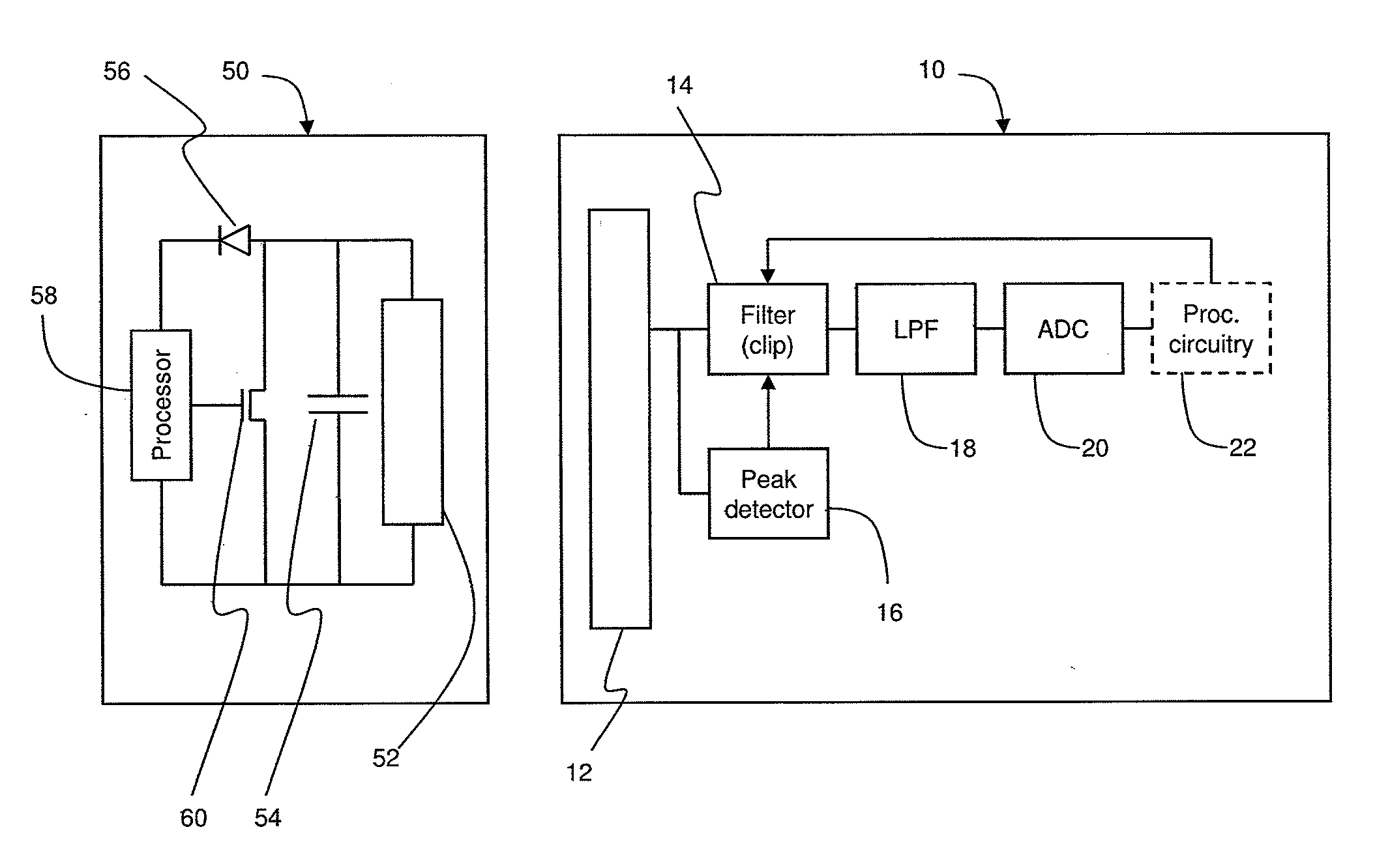
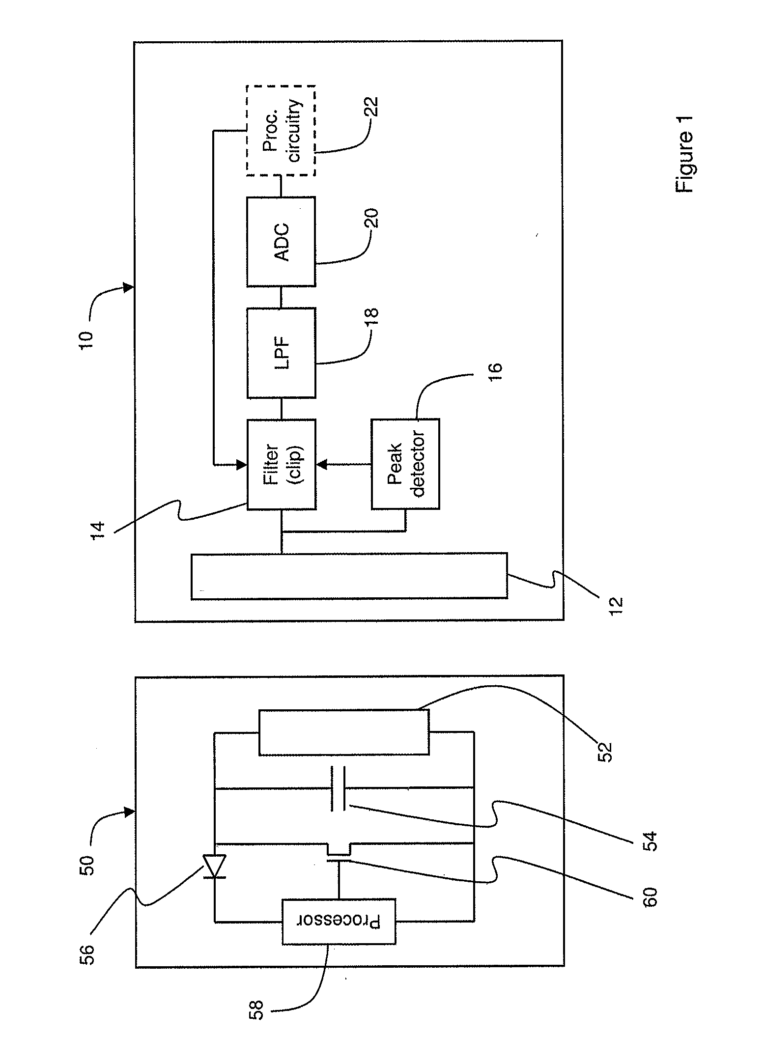
[0013]FIG. 1 is a schematic diagram of a Reader 10 and a Tag 50 according to embodiments of the present invention.

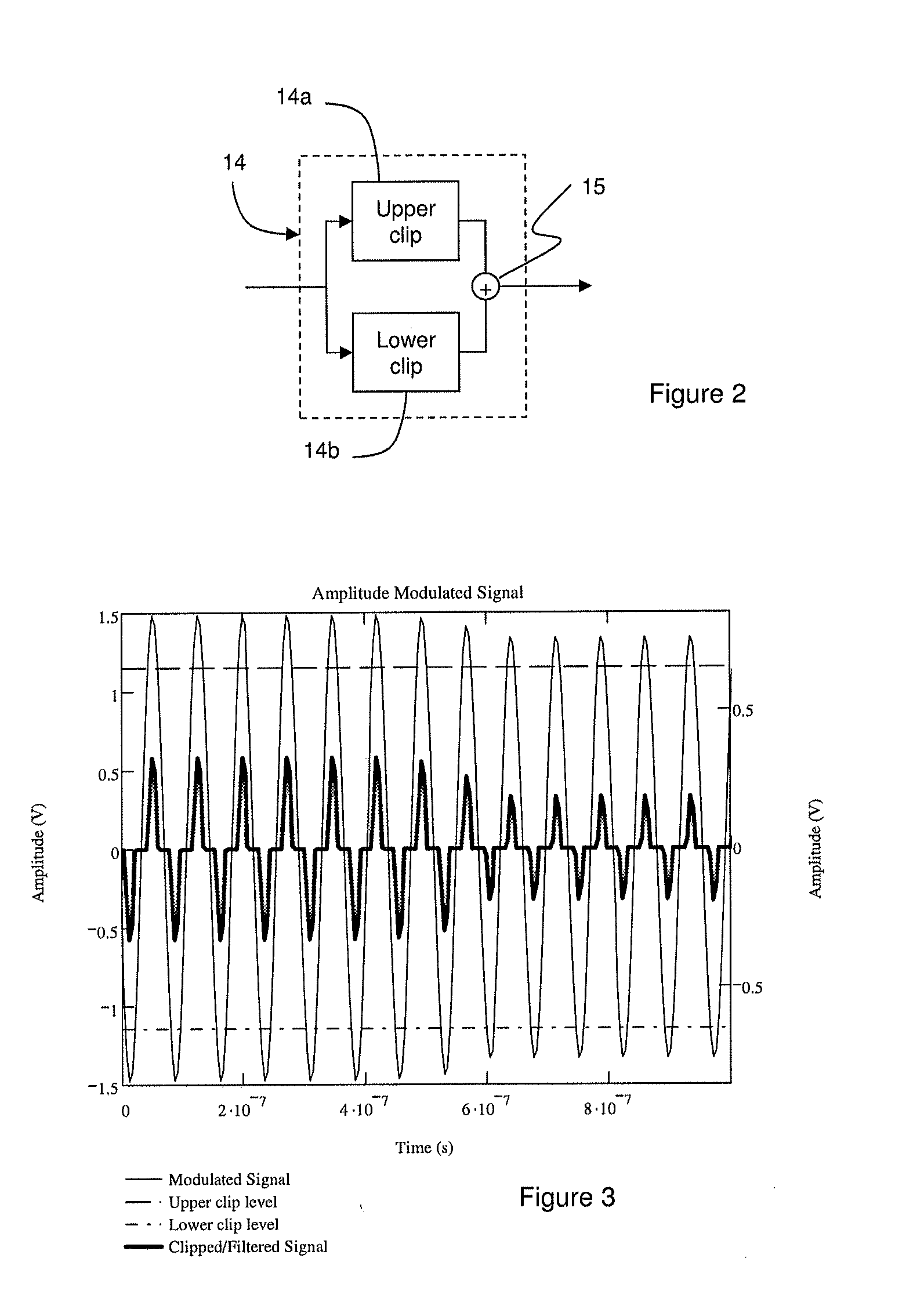
[0014]The Reader 10 comprises an antenna 12 with which signals can be transmitted and received, coupled to a receive Rx chain for processing signals received in the antenna 12. Those skilled in the art will appreciate that the antenna 12 will also be coupled to a transmit Tx chain in order to modulate the antenna signal to transmit data; however, this is not relevant to a description of the present invention and is therefore not illustrated for clarity. The first element in the Rx chain is an amplitude limiter 14 which applies upper and lower clipping levels to the signal in the antenna in a manner which will be described in further detail below. A peak detector 16 (also known as an envelope detector) is also coupled to the antenna 12, and sets the upper and lower clipping levels used in the amplitude limiter 14.

[0015]The clipping process may, in general, introduce high-...


PUM


Abstract

Methods and apparatus in a near-field communication system, in which a modulated signal received in a Reader is clipped by applying upper and lower clip levels. After clipping, the modulated part of the signal corresponds to a greater portion of the overall signal, and thus the requirements placed on an analogue-to-digital converter for the clipped signal are reduced. In a first mode of operation, prior to or at the start of reception of the load-modulated signal, the clip levels may be set in a feedforward manner on the basis of preset values or a detected change in the overall signal; in a second mode of operation, once the clipped signal is available, the clip levels may be set in a feedback manner on the basis of the clipped signal.

Description

TECHNICAL FIELD[0001]The present invention relates to telecommunications and particularly to a receiver for use in a near-field communications system.BACKGROUND[0002]Near-field communication (NFC) systems involve active devices, which have a power supply, and passive devices which typically do not. Active devices generate large radio-frequency signals which are used to communicate with the passive devices, but also to power them through magnetic induction. Thus, when the active device is brought sufficiently close to the passive device (typically under 20 cm), the RF field generated by the active device is used to power the passive device. In this application, active devices are termed Readers, while passive devices are termed Tags.[0003]The Reader of an NFC system, when communicating with a passive Tag, is required to provide a large input signal level so the energy in the signal can be harvested by the Tag in order to provide the power it needs to function correctly. During commun...

Claims


Application Information

Patent Timeline
IPC IPC(8): H04B5/00
CPCH04B5/72H04B5/79H03G3/3036H03G11/008H04B5/77
Inventor MCFARTHING, ANTHONY
Owner QUALCOMM TECH INT
Why Eureka
Try Eureka