
High-power tower receiver configuration

a receiver configuration and high-power technology, applied in the direction of mechanical equipment, machines/engines, light and heating equipment, etc., can solve the problems of lack of system control, the appearance of cracks is the most frequent structural flaw, and the difficulty of solar technology for superheated steam generation, etc., to achieve the effect of reducing the flow peak (w/m2), reducing the cost of the panel, and reducing the metal temperatur

Inactive Publication Date: 2014-06-05
ABENGOA SOLAR NEW TECH SA
View PDF4 Cites 1 Cited by
  • Summary
  • Abstract
  • Description
  • Claims
  • Application Information

AI Technical Summary

Benefits of technology

The patent describes a control strategy for a heliostat field in a solar power plant. The goal is to maintain optimal conditions for entry into the turbine and to provide energy as evenly as possible to minimize thermal stress on the receiver panels. The heliostat field is oriented towards either a central or peripheral module, depending on current needs and radiation availability. The configuration reduces metal temperatures in the peripheral modules for generation of superheated steam. The size of the panels can be reduced by half for a certain thermal power, while still maintaining the same flow peak. This results in lower thermal stress and longer service life of the materials. Overall, the control strategy improves the efficiency and stability of the solar power plant.

Problems solved by technology

The difficulty of solar technology for the generation of superheated steam lies in the demanding temperature conditions in which the receiver must operate.
Lack of system control, particularly in the case of transients, cloud passage, etc. mainly due to the bad thermal properties of superheated steam.
In both receivers, the most frequent structural flaw was the appearance of cracks.
The thermal stress due to large temperature differences led to the appearance of cracks in the interstitial welding between subpanels.
The problem of working at high pressures, which requires thicker pipe walls, necessitating high thermal gradients to transfer high power densities to the heat carrier fluid.
Analogously, patent US 2008 / 0078378 uses a trough receiver combining saturated and superheated steam receivers which, precisely due to their trough arrangement, have the aforementioned drawback that, due to heterogeneous temperature distribution, it requires special measures for protection against thermal stress in material, which has a negative impact on the receiver's service life.

Method used


Image

  • High-power tower receiver configuration
  • High-power tower receiver configuration
  • High-power tower receiver configuration

Examples


Embodiment Construction

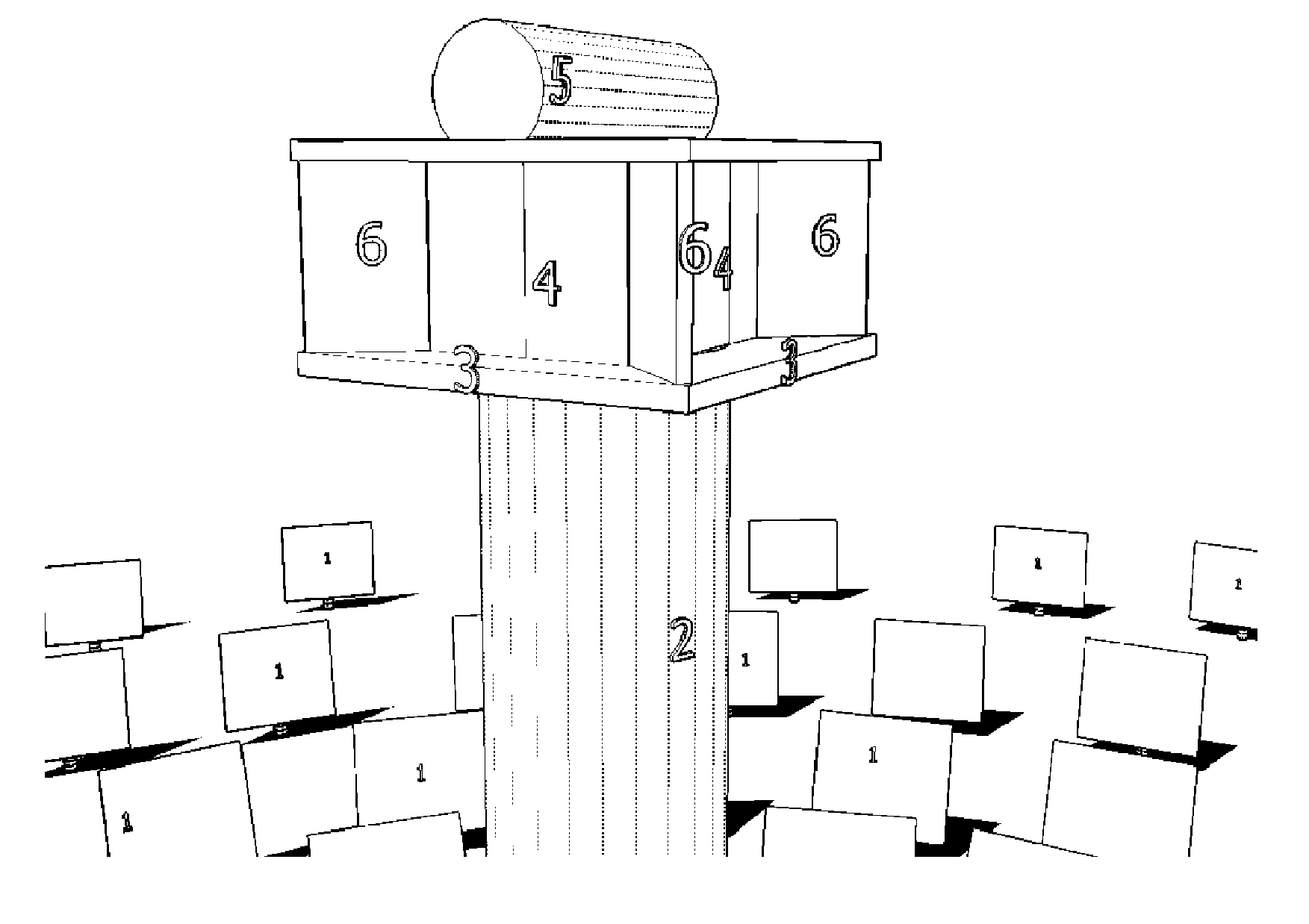
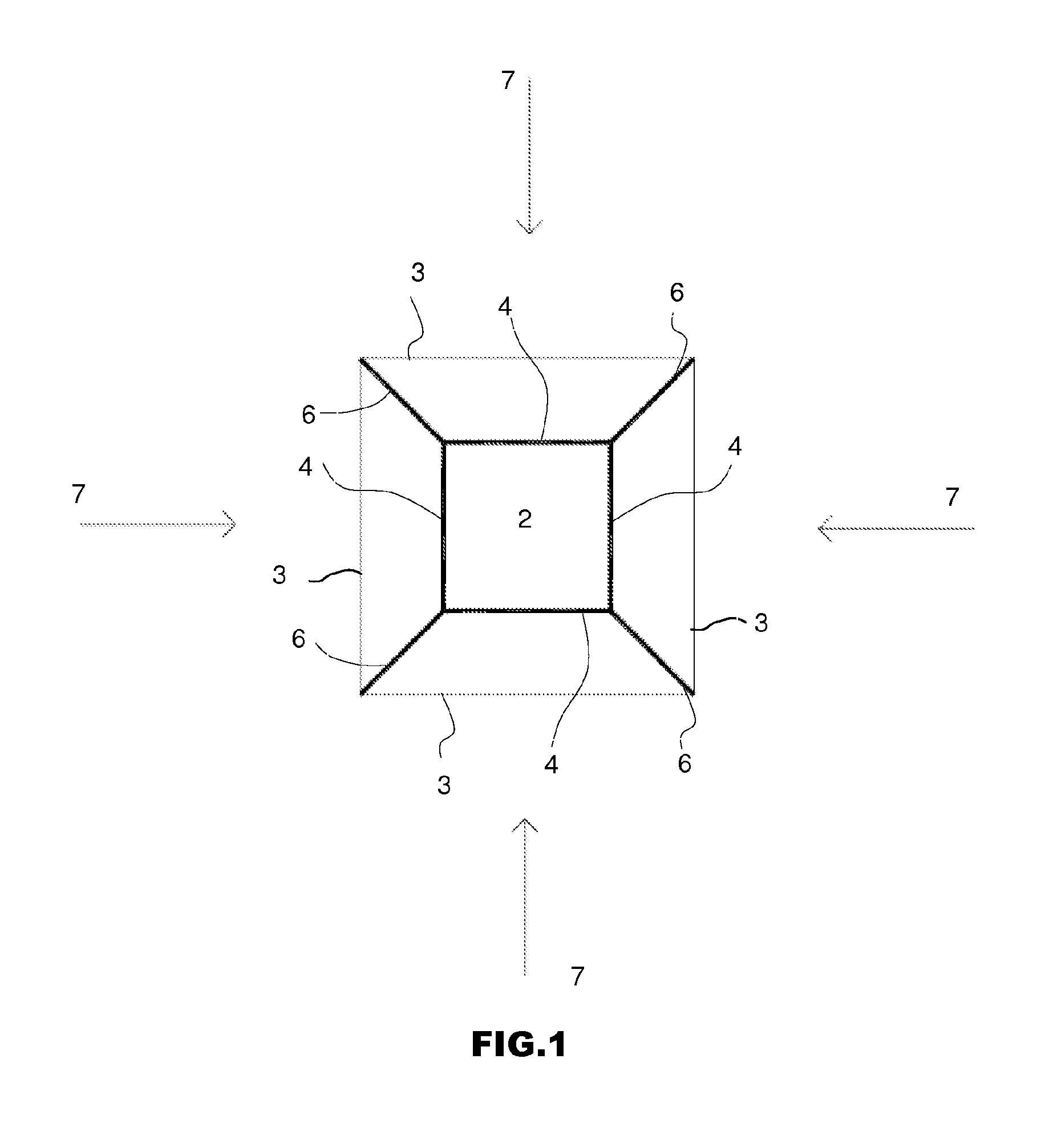
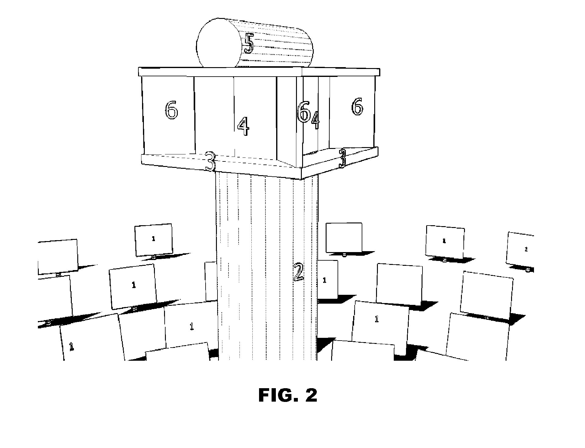
[0037]In both figures, numerical references correspond to the following parts and items:

[0038]1. Heliostats.

[0039]2. Central Tower.

[0040]3. Areas (orientations).

[0041]4. Central modules.

[0042]5. Container.

[0043]6. Peripheral modules.

[0044]7. Solar radiation

[0045]The details, forms, dimensions, and other accessory items, as well as the materials used in the high-power tower receiver configuration that is the object of this invention may be replaced as required by others that are technically equivalent and do not deviate from the essence of the invention or the scope defined by the following claims.

[0046]This invention concerns a solar receiver configuration located in a tower, with various orientations (or areas).

[0047]FIG. 1 depicts a preferred embodiment of the received by a solar power plant in accordance with this invention, composed of four areas (3), and a set of central modules (4) for the generation of saturated steam and a set of peripheral modules (6) for the superheating o...


PUM


Abstract

A receiver with a configuration of saturated and superheated steam solar modules in a tower solar concentration power plant. The configuration allows the incidence of radiation on both sides of the superheated steam module, providing significant benefits for its durability and global control of the power plant.

Description

CROSS-REFERENCES TO RELATED APPLICATIONS[0001]This application claims the benefit of the Spanish patent application No. P201001345 filed on Oct. 20, 2010, the entire disclosures of which are incorporated herein by way of reference.BACKGROUND OF THE INVENTION[0002]This invention concerns a configuration of the receivers in tower solar concentration plants with a physical separation between the evaporator, superheater, and the part for adaptive dynamic control of the heliostat field, in order to obtain superheated steam in an efficient and controlled manner, said configuration ensuring continued durability and normal operation of said solar plant in its various applications: electricity generation, process heat generation, solar fuel generation, and application to thermochemical processes.[0003]The panel configuration proposed is valid for plants where the heat carrier fluid is water-steam or any other fluid that is technically equivalent such as oils, salts, etc., and which do not de...

Claims


Application Information

Patent Timeline
Patent Type & Authority Applications(United States)
IPC IPC(8): F03G6/06F24S20/20
CPCY02E10/46F24S20/20F03G6/06Y02E10/40F03G6/063
Inventor MENDEZ MARCOS, JOSE MARIANAVIO GILABERTE, RAUL
Owner ABENGOA SOLAR NEW TECH SA
Learn More