
Furnaces and methods of reducing heat degrading of metal heating coils of furnaces

a technology of furnaces and heating coils, applied in the field of furnaces, can solve the problems of difficult heat transfer into the reaction tube, affecting the efficiency of furnaces, so as to reduce the combustibility of combustion media, reduce the peak heat generated, and reduce the effect of heat degradation

Inactive Publication Date: 2018-06-05
ATD COMBUSTORS
View PDF10 Cites 0 Cited by
  • Summary
  • Abstract
  • Description
  • Claims
  • Application Information

AI Technical Summary

Benefits of technology

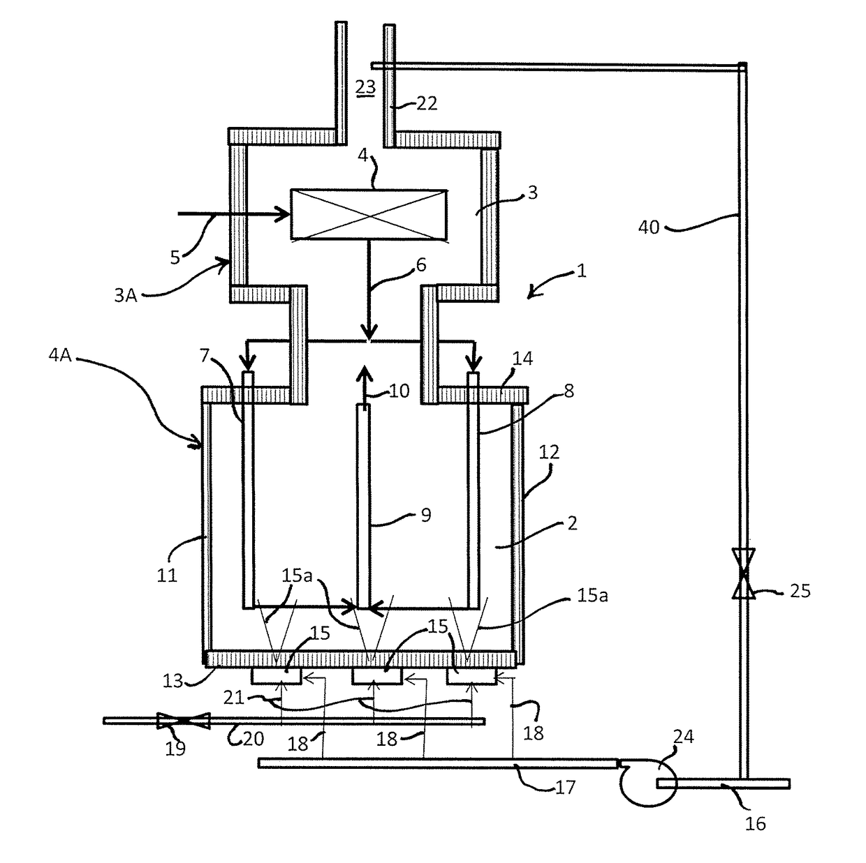
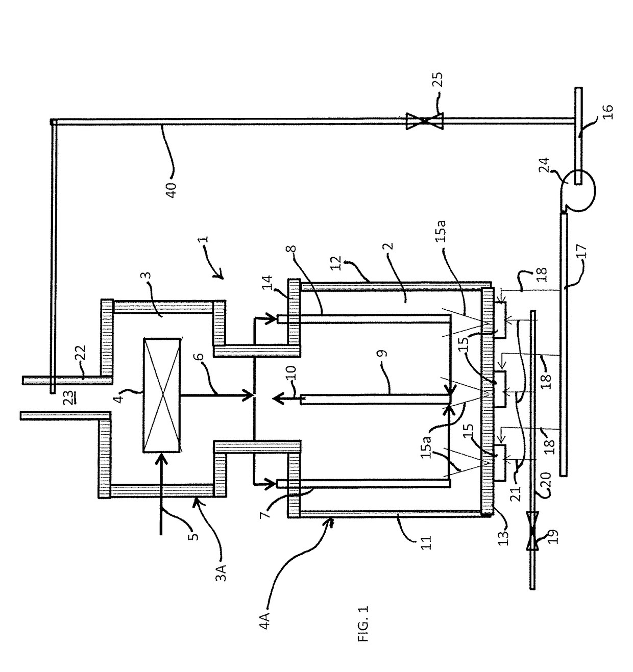
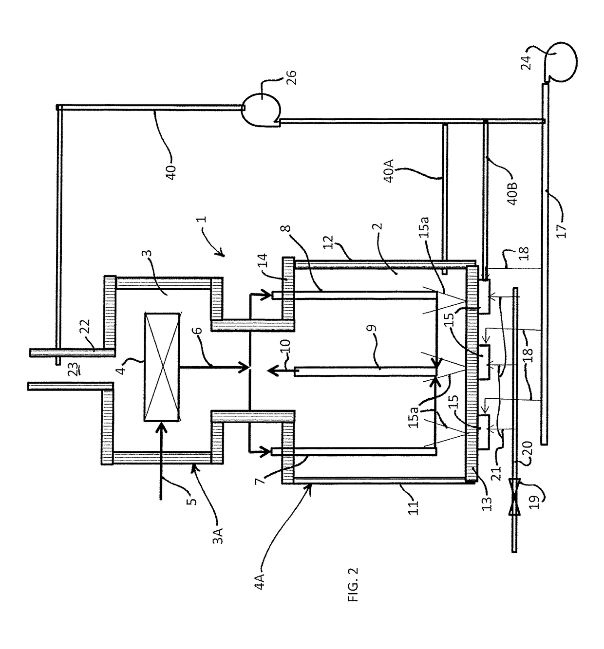
[0009]According to the principle of the invention, a method includes providing a furnace, the furnace includes a radiant heating zone having metal heating coils and burners, concurrently applying a combustion media, having a combustibility, and a diluent to the burners, the burners burning the combustion media producing flames heating the radiant heating zone, and the diluent reducing the combustibility of the combustion media for reducing peak heat generated by the flames for reducing heat degradation, such as fouling and cracking, of the metal heating coils. The combustion media includes fuel. In another embodiment, the combustion media includes fuel and air. The diluent is selected from a group consisting of flue gas, steam, hydrogen, carbon dioxide, and nitrogen. Flue gas and steam diluents each produce reduced soot formation by the flames, in accordance with the principle of the invention. Radiation flux directly correlates to flame emissivity. Accordingly, soot formation by the flames is reduced, which reduces flame emissivity of the flames, the ability of the flames to emit radiant energy, which, in turn, reduces local radiation flux, all of which contributes to reducing the temperature of the metal heating coils and reducing heat degradation of the metal heating coils, when the diluent is flue gas in one embodiment, and when the diluent is steam in another embodiment.
[0010]According to the principle of the invention, a method includes providing a furnace, the furnace includes a radiant heating zone having metal heating coils and burners, applying combustion media to the burners, the combustion media has a combustibility and includes, air, fuel, and a diluent in at least one of the air and the fuel, the burners burning the combustion media producing flames heating the radiant heating zone, and the diluent reducing the combustibility of the combustion media for reducing the peak heat generated by the flames for reducing heat degradation, such as fouling and cracking, of the metal heating coils. The combustion media includes fuel. In another embodiment, the combustion media includes fuel and air. The diluent is selected from a group consisting of flue gas, steam, hydrogen, carbon dioxide, and nitrogen. Flue gas and steam diluents each produce reduced soot formation by the flames, in accordance with the principle of the invention. Again, radiation flux directly correlates to flame emissivity. Accordingly, soot formation by the flames is reduced, which reduces flame emissivity of the flames, the ability of the flames to emit radiant energy, which, in turn, reduces local radiation flux, all of which contributes to reducing the temperature of the metal heating coils and reducing heat degradation of the metal heating coils, when the diluent is flue gas in one embodiment, and when the diluent is steam in another embodiment.
[0011]According to the principle of the invention, a method includes providing a furnace, the furnace includes a radiant heating zone having metal heating coils and burners, applying a combustion media to the burners, the combustion media having a combustibility, the burners burning the combustion media producing flames heating the radiant heating zone, applying a diluent to the radiant heating zone, and the diluent reducing the combustibility of the combustion media for reducing peak heat generated by the flames for reducing heat degradation, such as fouling and cracking, of the metal heating coils. The combustion media includes fuel. In another embodiment, the combustion media includes fuel and air. The diluent is selected from a group consisting of flue gas, steam, hydrogen, carbon dioxide, and nitrogen. Flue gas and steam diluents each produce reduced soot formation by the flames, in accordance with the principle of the invention. Again, radiation flux directly correlates to flame emissivity. Accordingly, soot formation by the flames is reduced, which reduces flame emissivity of the flames, the ability of the flames to emit radiant energy, which, in turn, reduces local radiation flux, all of which contributes to reducing the temperature of the metal heating coils and reducing heat degradation of the metal heating coils, when the diluent is flue gas in one embodiment, and when the diluent is steam in another embodiment.

Problems solved by technology

The coil will begin to deteriorate and become damaged or at least prone to damage when the coil is exposed to a temperature that exceeds the upper end of its nominal operating temperature range.
As a result, a typical heater must be monitored carefully at substantial cost to maintain specific temperature ranges.
This becomes problematic as deposits build up on the coil because more heat must be added to maintain the efficiency of the system.
Given the limitation of small tube volume to achieve short residence times and the high temperatures of the process, heat transfer into the reaction tube is difficult.
As a result, high heat fluxes are used and the operating tube metal temperatures are close to the mechanical limits for even exotic metallurgies.
In most cases, tube metal temperatures limit the extent to which residence time can be reduced.
Tube metal temperatures are also a limiting factor in determining the capacity of these radiant coils since more flux is required for a given tube when operated at higher capacity.
The exotic metal reaction tubes located in the radiant section of the cracking heater represent a substantial portion of the cost of the heater.
The results of these and other efforts, however, have not been entirely satisfactory, thereby necessitating further improvement in the art.

Method used


Image

  • Furnaces and methods of reducing heat degrading of metal heating coils of furnaces
  • Furnaces and methods of reducing heat degrading of metal heating coils of furnaces
  • Furnaces and methods of reducing heat degrading of metal heating coils of furnaces

Examples


Embodiment Construction

[0014]Furnaces and methods of reducing heat degrading of metal heating coils of furnaces are disclosed.

[0015]In general, an exemplary method includes providing a furnace, the furnace includes a radiant heating zone having metal heating coils and burners, concurrently applying a combustion media, having a combustibility, and a diluent to the burners, the burners burning the combustion media producing flames heating the radiant heating zone, and the diluent reducing the combustibility of the combustion media for reducing heat generated by the flames for reducing heat degradation, such as fouling and cracking, of the metal heating coils. The combustion media includes fuel. In another embodiment, the combustion media includes fuel and air. The diluent is selected from a group consisting of flue gas, steam, hydrogen, carbon dioxide, and nitrogen. Flue gas and steam diluents each produce reduced soot formation by the flames, in accordance with the principle of the invention. Radiation flu...


PUM

PropertyMeasurementUnit
operating temperatureaaaaaaaaaa
temperatureaaaaaaaaaa
outlet temperatureaaaaaaaaaa

Abstract

A method includes providing a furnace including a radiant heating zone having metal heating coils and burners, concurrently applying a combustion media, having a combustibility, and a diluent to the burners, the burners burning the combustion media producing flames heating the radiant heating zone, and the diluent reducing the combustibility of the combustion media for reducing heat generated by the flames for reducing heat degradation of the metal heating coils.

Description

CROSS-REFERENCE TO RELATED APPLICATIONS[0001]This application claims the benefit of U.S. Provisional Patent Application Ser. No. 62 / 051,822, filed Sep. 17, 2014, and U.S. Provisional Patent Application Ser. No. 62 / 165,718, filed May 22, 2015, the entire contents of which are incorporated herein by reference.FIELD OF THE INVENTION[0002]The present invention relates to furnaces.BACKGROUND OF THE INVENTION[0003]Water evaporation, process gas heating, steam cracking, and pyrolysis of hydrocarbons are examples of processes often carried out in tubular coils, the process coils, inside furnaces. These processes are often considered heart of the industrial plant and have significant influence on the economics of the overall industrial plant. The duration that heater or tubular coils can operate without failure depends on two primary factors: fouling and crack initiation. Fouling and cracking are forms of coil degradation. Fouling occurs when deposits, such as coke and scale, build up on the...

Claims


Application Information

Patent Timeline
Patent Type & Authority Patents(United States)
IPC IPC(8): F23C9/08F23L7/00
CPCF23C9/08F23L7/00F23L2900/07003F23L2900/07002F23C2202/20
Inventor TOQAN, MAJEDNAREDI, PRABHATAMIRA, NAJITSCHIRREN, STEFANPROSS, JORG
Owner ATD COMBUSTORS
Learn More