
Battery assembly for vehicle and vehicle having the same

a battery pack and vehicle technology, applied in battery/fuel cell control arrangement, battery/cell propulsion, electrochemical generators, etc., can solve the problems of affecting the electrical properties, performance, endurance of battery cells, and failure to uniformly supply cooling air to each battery pack module, etc., to increase the cooling performance and endurance of the battery pack module

Inactive Publication Date: 2014-05-22
HYUNDAI MOTOR CO LTD +1
View PDF3 Cites 16 Cited by
  • Summary
  • Abstract
  • Description
  • Claims
  • Application Information

AI Technical Summary

Benefits of technology

The present invention aims to solve the problem of an inflow air temperature difference between battery pack modules in the cooling of an existing battery pack, which results in air flow at different temperatures and decreased cooling performance and endurance of the battery modules. The present invention proposes a battery assembly with an internal duct and thermoelectric module(s) to reduce the temperature difference between battery rows and increase cooling performance and endurance of the battery modules. Furthermore, the battery assembly also includes a control unit to manage the thermoelectric module(s) and ensure optimal cooling performance. The battery housing is designed to be lightweight and rigid, with the internal duct providing an effect of reducing weight and the thermoelectric module(s) removing rigidity reinforcement to reduce weight. The technical effects of this invention include improved cooling performance and endurance of battery modules and reduced weight of the battery assembly.

Problems solved by technology

A high-capacity battery pack for an electric vehicle conventionally is designed to dispose battery pack modules within a restricted layout in series in order to satisfy power performance, and thus fails to uniformly supply cooling air to each battery pack module.
For example, assuming that the cooling air has a temperature of 35° C. at the inflow side and has an increment of 2° C. whenever passing through each battery pack module, a first battery pack module is supplied with the cooling air of 35° C., but a fourth battery pack module is supplied with the cooling air of 41° C. Thus, the cooling performance is remarkably reduced, and there are negative influences on the electrical properties, performance, and endurance of battery cells.
As a result, a performance difference between the battery pack modules of the battery pack occurs, with the result being that the performance and endurance of the battery pack are also reduced.
However, the above-described technology does not effectively deal with the air-conditioned air, but merely applies the thermoelectric module to conduct cooling / heating of the battery pack.
Mounting the thermoelectric module on the top of the battery pack module is problematic in that, due to cooling of only the top cell and heat collection, cooling of most of the other lower cells and heat collection are impossible.
Further, when only the top cell is cooled, there is a difference in a charging level due to a temperature difference between the cells.
This may exert a serious and negative influence on the performance of the battery pack module, and thus reduces the performance of the battery pack module.
When the thermoelectric module is mounted on each module, the weight and expenses are increased, which can become a serious problem.

Method used


Image

  • Battery assembly for vehicle and vehicle having the same
  • Battery assembly for vehicle and vehicle having the same
  • Battery assembly for vehicle and vehicle having the same

Examples


Embodiment Construction

[0036]Hereinafter, a battery assembly according to an exemplary embodiment of the present invention and a vehicle having the same will be described in detail with reference to the accompanying drawings

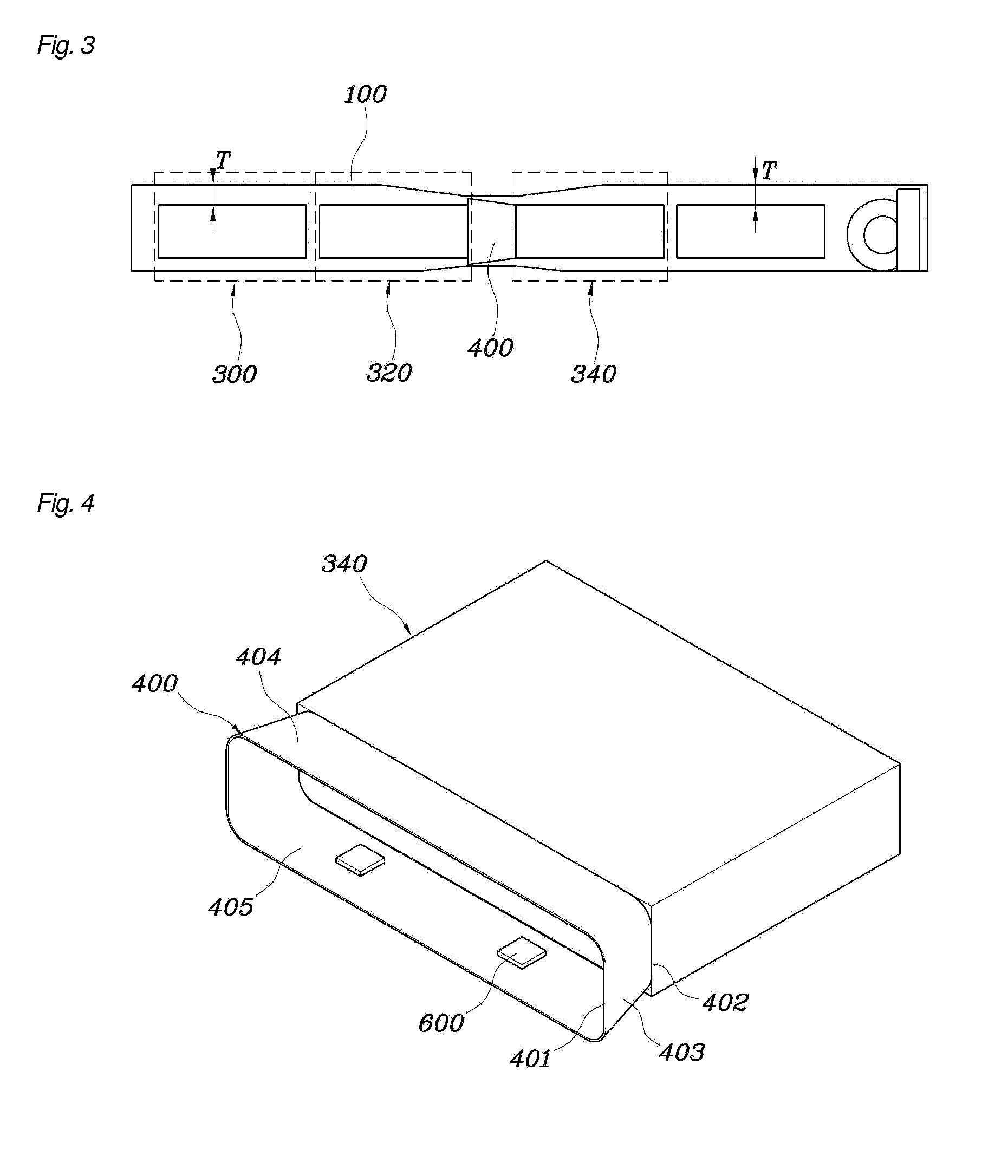
[0037]FIG. 1 is a perspective view of a battery assembly for a vehicle according to an embodiment of the present invention. FIG. 2 is a plan view of the battery assembly shown in FIG. 1, and FIG. 3 is a side view of the battery assembly shown in FIG. 1.

[0038]The battery assembly for a vehicle of the present invention includes: a battery housing 100 in which air-conditioned air F is introduced into the front thereof and is discharged from the rear thereof; a plurality of battery rows 300 disposed in the battery housing 100 so as to be perpendicular to a flow of the air-conditioned air F, form through-holes 302 through which the air-conditioned air F flows, and being disposed in parallel to each other, one after another, from the front to the rear of the battery housing; and an internal ...


PUM

PropertyMeasurementUnit
temperatureaaaaaaaaaa
cross-sectional areaaaaaaaaaaa

Abstract

A battery assembly for a vehicle and a vehicle having the battery assembly are provided. The battery assembly includes a battery housing in which air-conditioned air is introduced into a front thereof and is discharged from a rear thereof, a plurality of battery rows that are disposed in the battery housing so as to be perpendicular to a flow of the air-conditioned air, the battery rows forming through-holes through which the air-conditioned air flows, and being disposed in parallel to each other, one after another, from the front to the rear of the battery housing, and an internal duct that is disposed between a pair of adjacent battery rows among the battery rows having open front and rear end faces so that the air-conditioned air flows into the front end face through the rear end face.

Description

CROSS-REFERENCE TO RELATED APPLICATION[0001]This application claims under 35 U.S.C. §119(a) the benefit of Korean Patent Application No. 10-2012-0130256 filed Nov. 16, 2012, the entire contents of which are incorporated herein by reference.BACKGROUND OF THE INVENTION[0002](a) Field of the Invention[0003]The present invention relates to a battery assembly for a vehicle capable of effectively managing air-conditioned air and reducing a deviation in battery temperature distribution, and a vehicle having the same.[0004](b) Description of the Related Art[0005]The present invention relates to a uniform, effective cooling structure of a high-capacity battery pack of a vehicle. To dispose the battery pack in a restricted space and to uniformly cool the battery pack, a temperature and flow of air on an inlet side should be constant, and air (high temperature) on an outlet side should not influence the air on the inlet side. To this end, it is desirable to optimize the structure of the batter...

Claims


Application Information

Patent Timeline
Patent Type & Authority Applications(United States)
IPC IPC(8): H01M10/50
CPCH01M10/625H01M10/637H01M10/663H01M10/6563H01M10/6556B60L2240/545B60L58/26B60L50/64Y02T10/70Y02E60/10H01M10/60B60K11/06H02K9/04B60L50/50
Inventor KIM, SANG JUNOH, SE MINJEONG, WOO YEOL
Owner HYUNDAI MOTOR CO LTD
Learn More