Illumination apparatus and image reading apparatus
an image reading and illumination apparatus technology, applied in mechanical apparatus, lighting and heating apparatus, instruments, etc., can solve the problems of reducing illumination depth, unable to achieve high image quality, and inability to have an illumination area with stable light intensity, etc., to achieve enhanced condensing efficiency, stable light intensity, and increased illumination depth
- Summary
- Abstract
- Description
- Claims
- Application Information
AI Technical Summary
Benefits of technology
Problems solved by technology
Method used
Image

Examples
first embodiment
Image Reading Apparatus
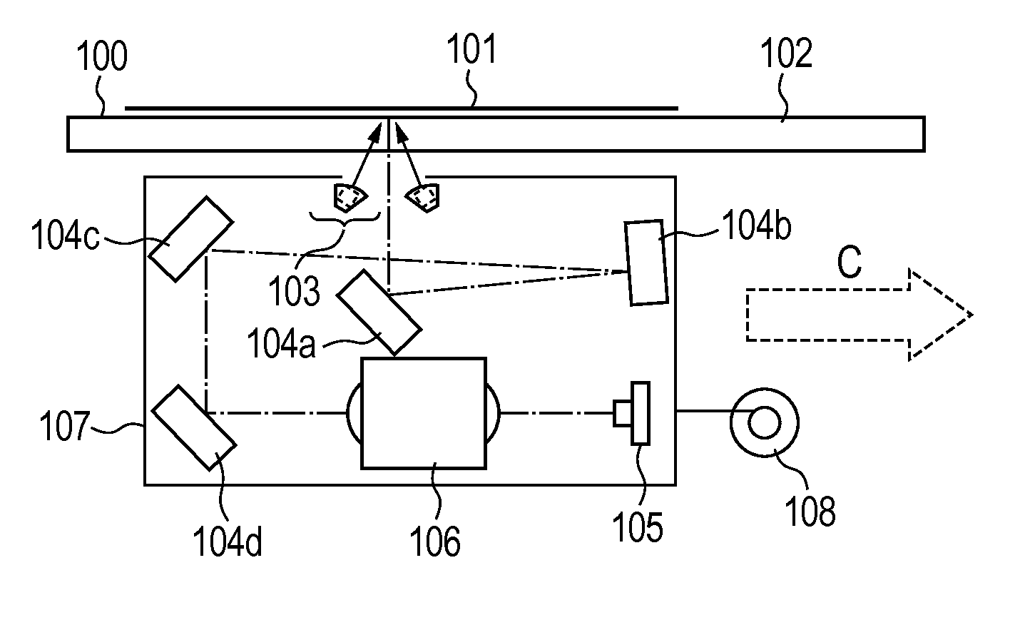
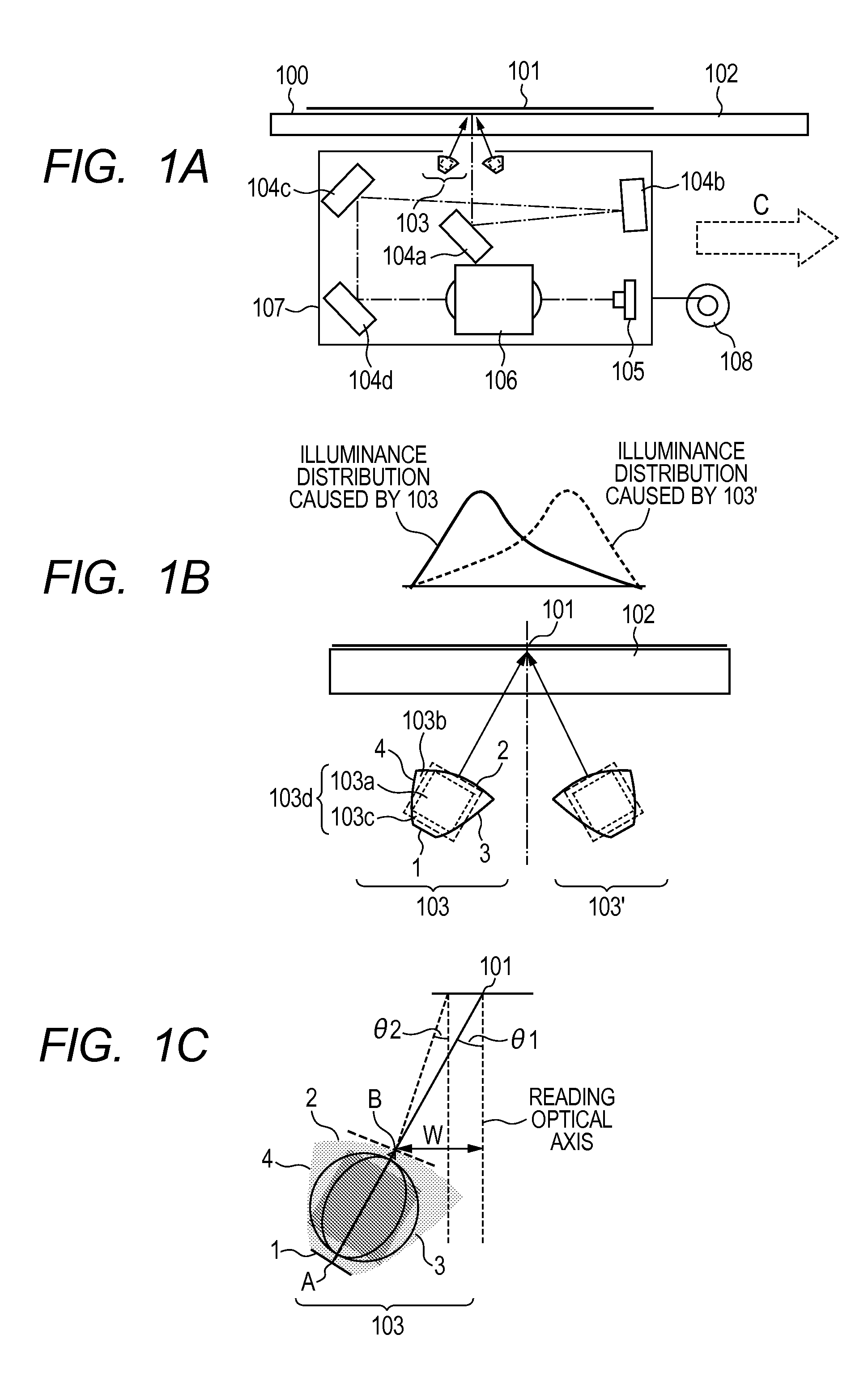
[0028]FIG. 1A is a schematic diagram showing the basic construction of the relevant portion of an image reading apparatus 100 equipped with an illumination apparatus according to an embodiment of the present invention. An integrated scanning optical system unit (which is sometimes referred to also as a “carriage unit”) 107 moving in an integrated manner in the direction of arrow C includes an illumination apparatus 103 for illuminating an original 101 placed on an original platen glass (platen) 102.
[0029]The integrated scanning optical system unit 107 also includes a reading unit (line sensor or image sensor) 105, which serves as an image pickup element that reads beams coming from the illuminated original 101. The integrated scanning optical system unit 107 further includes a plurality of turn back mirrors 104a to 104d that guide light beams coming from the original 101 to the reading unit 105 and an imaging optical system (imaging lens) 106 that converges l...
second embodiment
[0058]FIG. 5 is a cross sectional view on a sub-scanning section of the original illumination apparatus according to this embodiment. This apparatus differs from the apparatus according to the first embodiment in that the first optical surface 11 is an incidence surface, a light source unit 203d including a plurality of white LED light sources 203a arranged in a single array along the main scanning direction is used as the light source unit and arranged immediately below the first optical surface 11. The construction of the image reading apparatus is the same as the first embodiment and will not be described further. In the following, the illumination apparatus according to this embodiment will be described in detail.
[0059]FIG. 5 is a cross sectional view on sub-scanning section of a light guide 203b of the illumination apparatus 203 for image reading according to this embodiment. FIG. 6 is a perspective view of the light guide 203b. As with the light guide according to ...
third embodiment
[0065]FIG. 9 is a cross sectional view on a sub-scanning section of a light guide 303b of an illumination apparatus 303 according to a third embodiment. FIG. 10 is a perspective view of the light guide 303b. The light guide according to this embodiment differs from those according to the first and second embodiments that the first optical surface 21 is an incident surface, and the light emitting element 303a of the light source unit 303d is a surface light-emitting device (high illuminance EL light source) which is arranged immediately below the first optical surface 21. The construction of the image reading apparatus is the same as the first and second embodiments and will not be described further.
[0066]As with the light guides according to the first and second embodiments, the light guide 303b according to this embodiment has a first optical surface 21, a light exit surface 22, a first reflective side surface 23, and a second reflective side surface 24, the first and s...
PUM
 Abstract
Description
Claims
Application Information
 - R&D
- Intellectual Property
- Life Sciences
- Materials
- Tech Scout
- Unparalleled Data Quality
- Higher Quality Content
- 60% Fewer Hallucinations
Browse by: Latest US Patents, China's latest patents, Technical Efficacy Thesaurus, Application Domain, Technology Topic, Popular Technical Reports.
© 2025 PatSnap. All rights reserved.Legal|Privacy policy|Modern Slavery Act Transparency Statement|Sitemap|About US| Contact US: help@patsnap.com