
Safety apparatus for brake of vehicle

a safety apparatus and brake technology, applied in the direction of rotary clutches, braking systems, fluid couplings, etc., can solve the problems of lowering the negative pressure of the intake manifold, affecting the safety of vehicles, so as to prevent brake fade or brake vapor lock, the effect of preventing accidents

Active Publication Date: 2014-05-22
HANJUNG
View PDF4 Cites 0 Cited by
  • Summary
  • Abstract
  • Description
  • Claims
  • Application Information

AI Technical Summary

Benefits of technology

The present invention provides a safety apparatus for the brakes of a vehicle that can stop the engine and prevent accidents caused by sudden acceleration or stopping of the engine due to malfunctions of the parts relating to sudden acceleration. The apparatus uses an auxiliary vacuum pump to normally operate the brakes when the intake manifold does not maintain a vacuum due to a sudden acceleration or stopping of the engine. The apparatus stops the engine and prevents accidents when the brakes are abnormally operated due to lack of vacuum in the brake booster, which can occur due to malfunction of the parts relating to sudden acceleration or due to weather conditions. The brakes normally operate to prevent accidents during sudden acceleration or operation of the engine, and the apparatus prevents brake fade or vapor lock that may occur when driving a diesel vehicle on a downhill road.

Problems solved by technology

Accordingly, there is a problem in that the booster fails to amplify a pressure therein so that a vehicle cannot be stopped even though the driver pushes the brake pedal to increase the hydraulic pressure in order to stop the vehicle.
On the other hand, when using an automatic transmission, since an initial speed of a vehicle is determined based on a position of a transmission gear of the transmission, the vehicle may start at a rapid speed so as to cause a collision accident.
Further, an Electronic Control System (ECU) may make a throttle body malfunction, thereby lowering the negative pressure of the intake manifold.
In addition, the ECU may fail to control an ignition control apparatus to make ignition timing irregular, thereby lowering the negative pressure of the intake manifold.

Method used


Image

  • Safety apparatus for brake of vehicle
  • Safety apparatus for brake of vehicle
  • Safety apparatus for brake of vehicle

Examples


embodiment

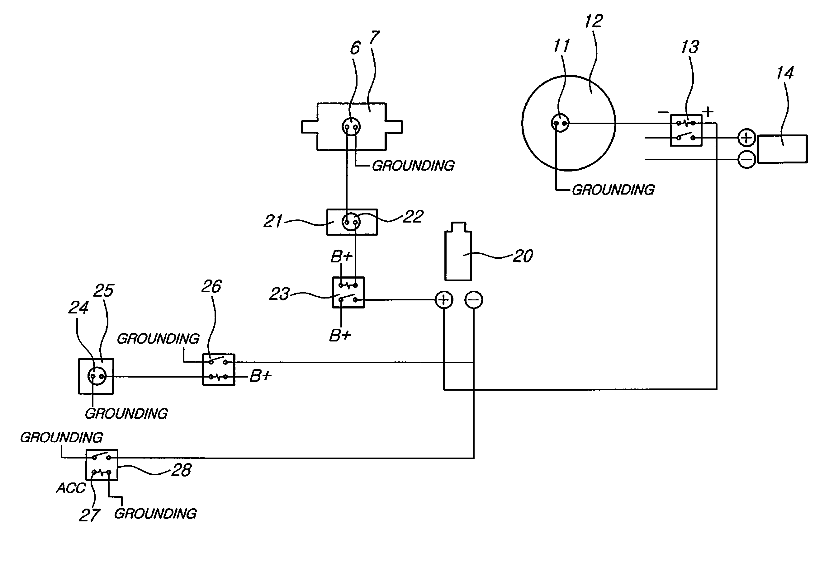
[0040]In a case where a negative pressure is measured when an engine is in a sudden acceleration state shown in FIG. 2, the vacuum switch 6 receives a signal and operates the vacuum pump 20 whenever a driver pushes the brake pedal 21.

[0041]Here, the four pin relay 23 is used to stably supply electric power to the vacuum pump 20.

[0042]Here, the vacuum pump 20 operates when the side brake is locked, and ceases to operate when the side brake is unlocked.

[0043]When the brake booster 12 is lack of a vacuum pressure, the vacuum switch 11 operates and the negative terminal (−) of the four pin relay 13 is connected to the positive terminal (+) of the vacuum pump 20 so as to isolate a supply of electric power to the fuel motor 14.

[0044]As described above, the brake switch 22, the side switch 24 and the ACC 27 electrically connected to the first line and the second line control the vacuum pump 20 and maintain the boosters 17 and 12 in a vacuum state, so that the driver can operate the brake s...


PUM


Abstract

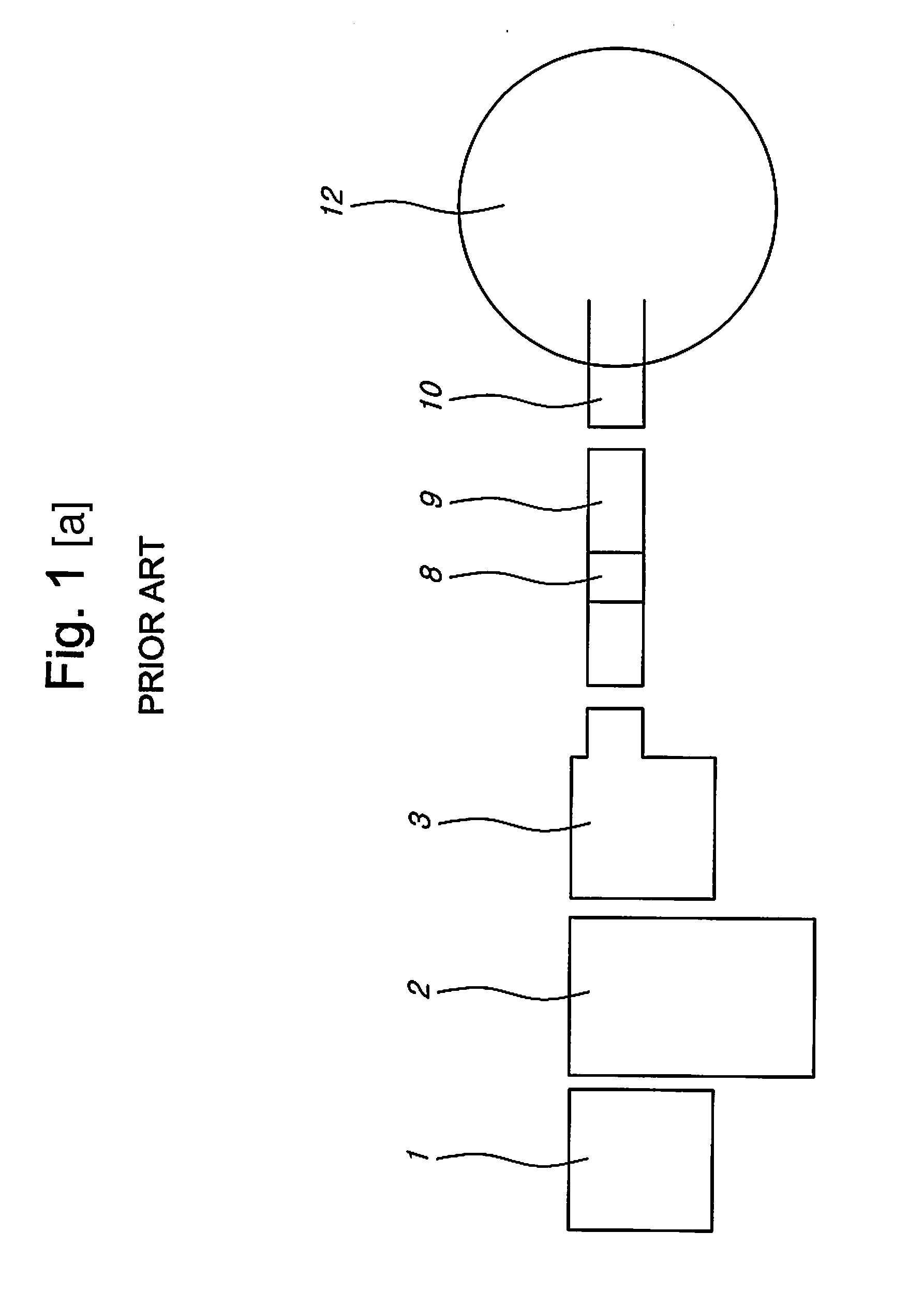
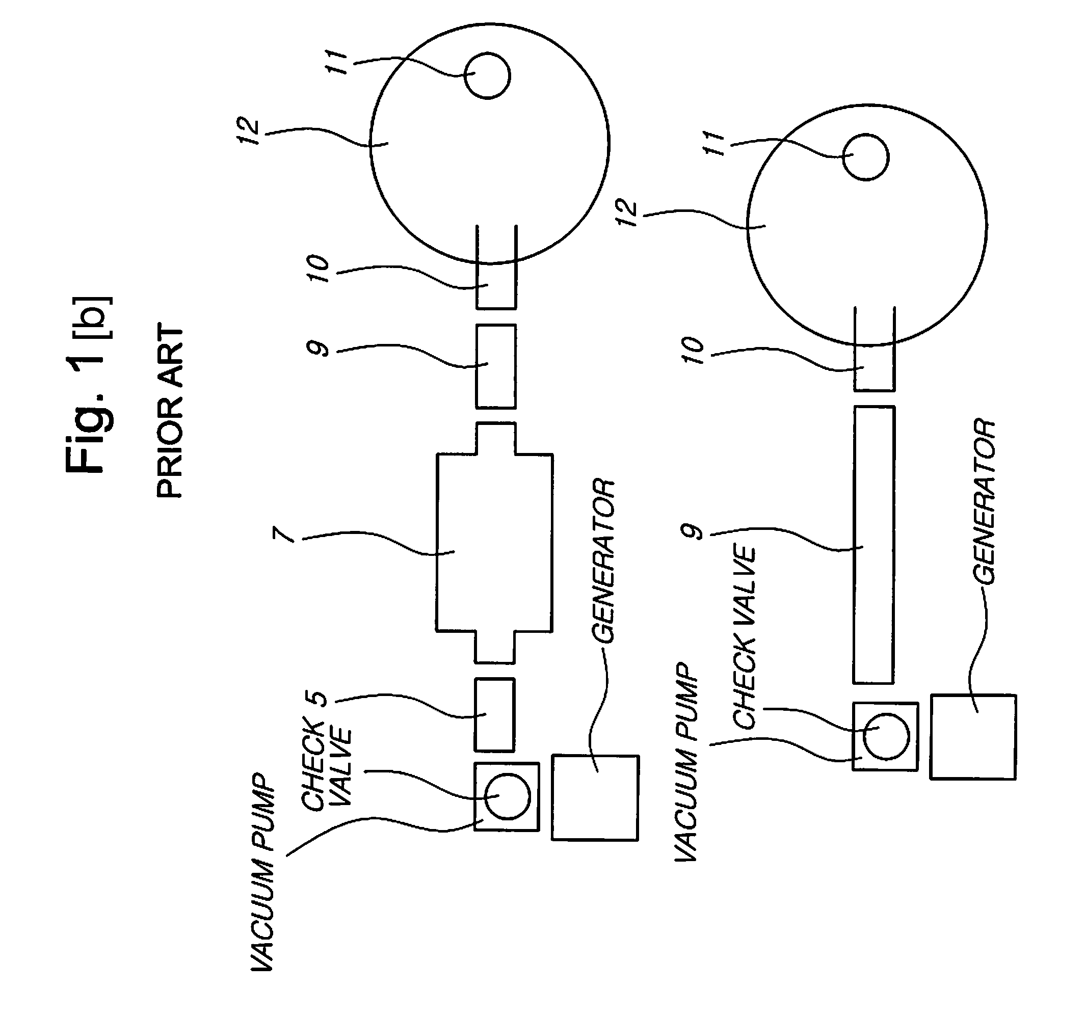
The safety apparatus for a brake of a vehicle includes a first line and a second line. The first line includes an exhaust manifold, an engine, an intake manifold, a check valve, a vacuum hose, a vacuum switch, a booster, a check valve, a vacuum hose, a negative connection portion, a vacuum switch and a brake booster, and the second line includes a vacuum hose, a check valve, a booster, a check value, a vacuum hose and a vacuum pump, which are connected to the negative connection portion. The apparatus can isolate a supply of electric power to a fuel motor to stop starting of the engine when the brake booster lacks a vacuum because of a deterioration of a performance of an auxiliary vacuum pump, and enable the brake to normally operate so as to prevent an accident even though a sudden acceleration occurs or the engine suddenly stops.

Description

BACKGROUND OF THE INVENTION[0001]1. Field of the Invention[0002]The present invention relates to a safety apparatus for a brake of a vehicle, and more particularly a safety apparatus for a brake of a vehicle with an independent brake safety apparatus, in which an auxiliary vacuum pump is driven to normally operate a brake when an intake manifold does not maintain a vacuum due to a sudden acceleration or a stopping of an engine because an ECU, a throttle valve and wire, which are parts relating to the sudden acceleration, malfunction due to a weak durability of the parts caused by impact or due to an introduction of rain water caused by a weak durability and a defect of an exterior material, in which a supply of electric power to a fuel motor is blocked so as to stop an operation of an engine when the brake is abnormally operated because a brake booster is lack of vacuum due to a deterioration of the auxiliary vacuum pump, in which the brake normally operates to prevent an accident e...

Claims


Application Information

Patent Timeline
Patent Type & Authority Applications(United States)
IPC IPC(8): B60T17/22
CPCB60T13/46B60T17/02B60T17/226B60T7/12B60T13/74
Inventor KANG, PIL-SOO
Owner HANJUNG
Learn More