
Running system of work vehicle

a running system and work vehicle technology, applied in vehicle position/course/altitude control, process and machine control, instruments, etc., can solve problems such as deteriorating work efficiency, work needs to be stopped, and not checked whether or not there is any abnormality in sensors, so as to facilitate work and the like, prevent accidents, and operate.

Active Publication Date: 2017-09-19
YANMAR POWER TECHNOLOGY CO LTD
View PDF23 Cites 6 Cited by
  • Summary
  • Abstract
  • Description
  • Claims
  • Application Information

AI Technical Summary

Benefits of technology

[0018]By using the above-described means, the operator who operates the autonomous traveling work vehicle can easily recognize that the accompanying traveling work vehicle approaches the field end, and can operate, work and the like at ease.
[0019]Moreover, the operator can easily recognize whether or not the autonomous traveling work vehicle has any abnormality before work, and can operate, work, and the like at ease, and an accident can be prevented.

Problems solved by technology

However, in the technique in Patent Document 1, while it is checked whether or not there is malfunction during the automatic traveling, it is not checked whether or there is any abnormality in sensors before the automatic traveling.
Accordingly, in the case where an actuator is not used at the time of automatic traveling start, and the actuator is actuated in the middle of work, if the actuation is abnormal, the work needs to be stopped, which deteriorates work efficiency.
Especially, if there is any abnormality in a sensor or an actuator concerned with stop, the stop may be disabled even if the stop is attempted after the traveling starts, which can lead to an accident.
When this autonomous traveling work vehicle approaches the field end, it rapidly decreases a speed or stops, so that the operator may be bewildered, and sudden stop causes a risk of collision.

Method used


Image

  • Running system of work vehicle
  • Running system of work vehicle
  • Running system of work vehicle

Examples


Embodiment Construction

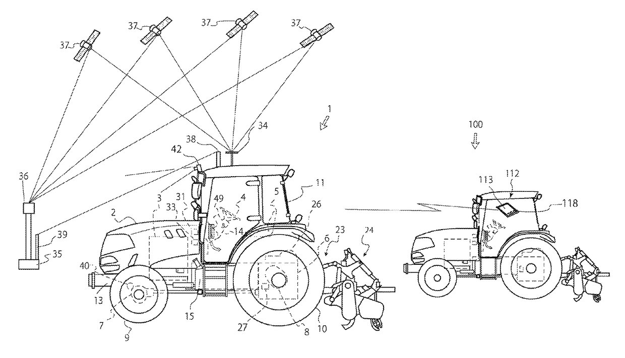
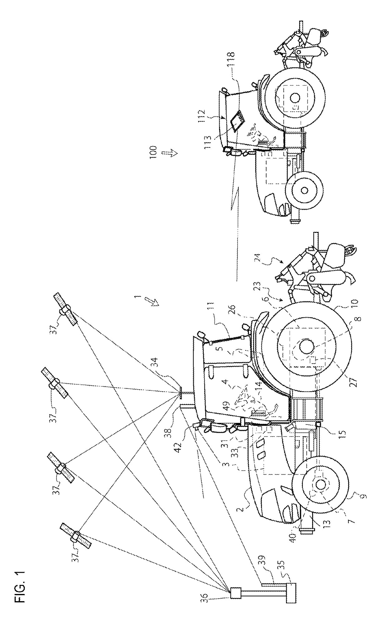
[0025]An example will be described in which an autonomous traveling work vehicle 1 that can autonomously travel, utilizing a satellite positioning system is a tractor, and a rotary tilling device 24 is attached to a rear portion of the autonomous traveling work vehicle 1 as a work machine. However, the work vehicle is not limited to the tractor, but may be a combine harvester or the like. Moreover, the work machine is not limited to the rotary tilling device, but may be a furrower, a mower, a rake, a seeding machine, a fertilizer, a wagon or the like.

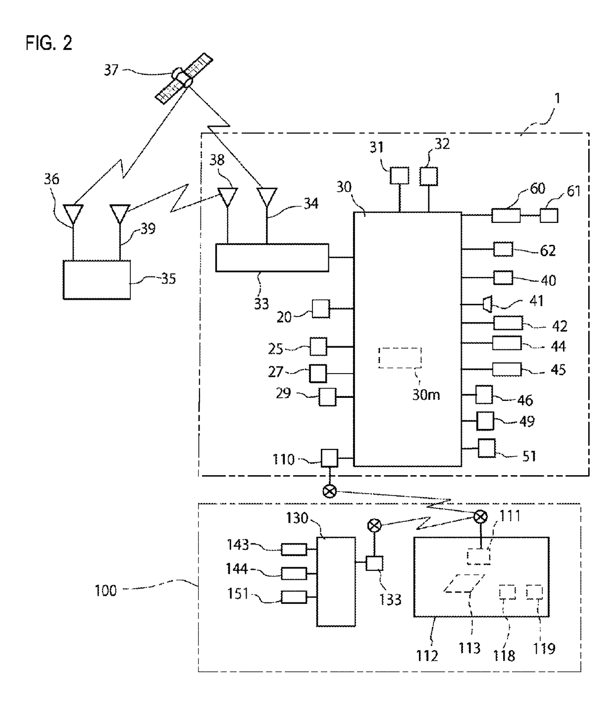
[0026]In FIGS. 1 and 2, a whole configuration of a tractor, which is an autonomous traveling work vehicle 1, will be described. An engine 3 is provided inside a hood 2, a dashboard 14 is provided inside a cabin 11 in the rear of the hood 2, and a steering handle 4, which is steering operation means, is provided on the dashboard 14. Rotation of the steering handle 4 brings about rotation of a direction of front wheels 9, 9 through a stee...


PUM


Abstract

A parallel operation work vehicle for enabling operation of an autonomous work vehicle by a long distance operating device installed in an accompanying work vehicle for performing work while accompanying the autonomous work vehicle, wherein the accompanying work vehicle is provided with a display and a speaker as notification means, the notification means is capable of communicating with the autonomous work vehicle through a communication device, and, when a distance to the edge of the cultivated field from the autonomous work vehicle approaches a set distance, a control device transmits a signal to a control device of the accompanying work vehicle through the communication device and issues a warning through the notification means.

Description

[0001]This is the U.S. national stage of application No. PCT / JP2015 / 064576, filed on May 21, 2015. Priority under 35 U.S.C. §119(a) and 35 U.S.C. §365(b) is claimed from Japanese Application No. 2014-106557, filed May 22, 2014, and Japanese Application No. 2014-106559, filed May 22, 2014 the disclosures of which are also incorporated herein by reference.TECHNICAL FIELD[0002]The present invention relates to a technique for surely performing accompanying traveling work in a traveling system of an autonomous traveling work vehicle that can autonomously travel along a set traveling route, utilizing a satellite positioning system, and a work vehicle that travels and works, accompanying the autonomous traveling work vehicle.BACKGROUND ART[0003]Conventionally, there has been publicly known a technique in which a controller determines whether or not an automatic traveling machine operates erroneously by performing positioning with signals from GPS satellites, and confirming or checking a po...

Claims


Application Information

Patent Timeline
Patent Type & Authority Patents(United States)
IPC IPC(8): B60W10/06B60W50/14G05D1/00A01B69/04A01B69/00G05D1/02B60W10/18B60W30/14B60W50/02
CPCA01B69/008A01B69/00B60W10/06B60W10/18B60W30/143B60W50/0205B60W50/14G05D1/0011G05D1/0088G05D1/02G05D1/0278G05D1/0291B60W2050/022B60W2050/0215B60W2050/143B60W2050/146B60W2420/42B60W2550/10B60W2720/10G05D2201/0201G05D1/0293B60W2554/00
Inventor YOKOYAMA, KAZUHISA
Owner YANMAR POWER TECHNOLOGY CO LTD
Learn More