
Method for controlling a hybrid drive train of a motor vehicle

a hybrid drivetrain and motor vehicle technology, applied in vehicle position/course/altitude control, process and machine control, instruments, etc., can solve the problem of necessary complete reduction of torque, no account of possible change of transmission input speed during closing process, and no longer sufficient power output of electric machine. problem, to achieve the effect of reducing the thermal loading of the separator clutch

Active Publication Date: 2014-05-15
ZF FRIEDRICHSHAFEN AG
View PDF10 Cites 14 Cited by
  • Summary
  • Abstract
  • Description
  • Claims
  • Application Information

AI Technical Summary

Benefits of technology

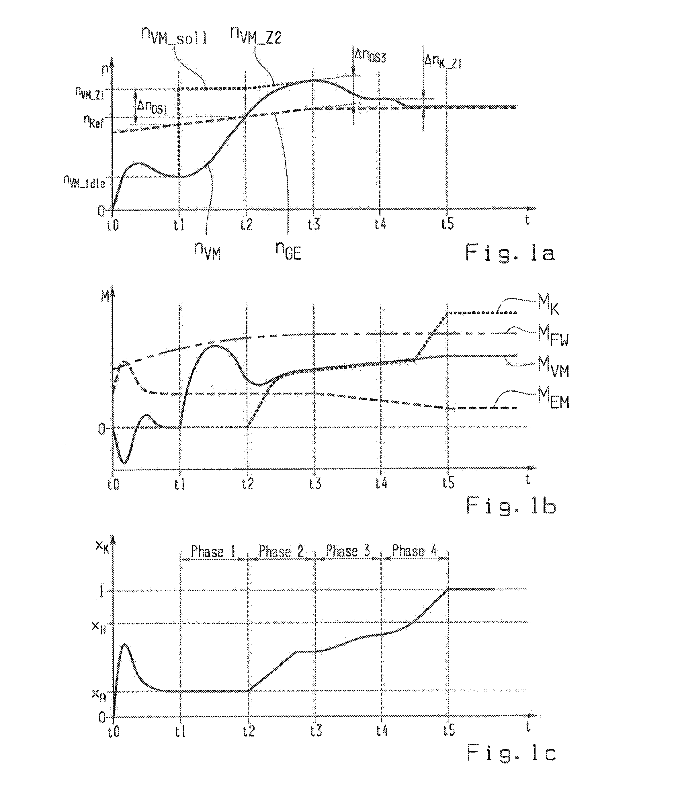
The present invention provides an improved method for controlling a hybrid drive-train of a motor vehicle. The method allows for faster and more comfortable acceleration of the internal combustion engine without any assistance from an auxiliary drive. The internal combustion engine automatically accelerates to the transmission input speed and is then connected to the input shaft by closing the separator clutch. This acceleration takes place with a time overlap, resulting in faster acceleration and reduced torque interruption. The target speed of the internal combustion engine is set higher to avoid overshooting and allow for sufficient scope for regulating and adjusting the engine speed. The speed regulation of the internal combustion engine is controlled in two phases, with a speed offset of around 50 to 200 revolutions per minute above the transmission input speed to avoid uncomfortable jerk. The method reduces the thermal loading of the separator clutch and reduces the rotational speed difference at the separator clutch to further reduce the load on the clutch.

Problems solved by technology

A power output of the electric machine which is no longer sufficient for this can occur owing to a maximum torque of the electric machine predetermined by design and / or owing to an electrical energy accumulator which is no longer sufficiently charged.
Since the mass moment of inertia that results from the rapid acceleration of the internal combustion engine and acts upon its driveshaft is relatively large and difficult to control, the problem exists of how the internal combustion engine can be synchronized rapidly and as exactly as possible without overshooting the target rotational speed.
On the other hand the load reduction of the internal combustion engine after or during the closing of the separator clutch should also take place as quickly as possible, but this conflicts with the sometimes necessary complete reduction of the torque produced in order to terminate the acceleration.
In this method, however, no account is taken of a possible change of the transmission input speed during the closing process of the separator clutch, caused by an acceleration or deceleration of the motor vehicle.
From the torque variations in the average time diagram shown in FIG. 3 thereof it can be seen that the acceleration of the internal combustion engine to the transmission input speed and the closing of the separator clutch to its gripping point take a relatively long time, and that the torque produced by the internal combustion engine for acceleration is again reduced to zero in order to limit the speed increase, which delays and makes more difficult the subsequent load build-up of the internal combustion engine.

Method used


Image

  • Method for controlling a hybrid drive train of a motor vehicle
  • Method for controlling a hybrid drive train of a motor vehicle
  • Method for controlling a hybrid drive train of a motor vehicle

Examples


Embodiment Construction

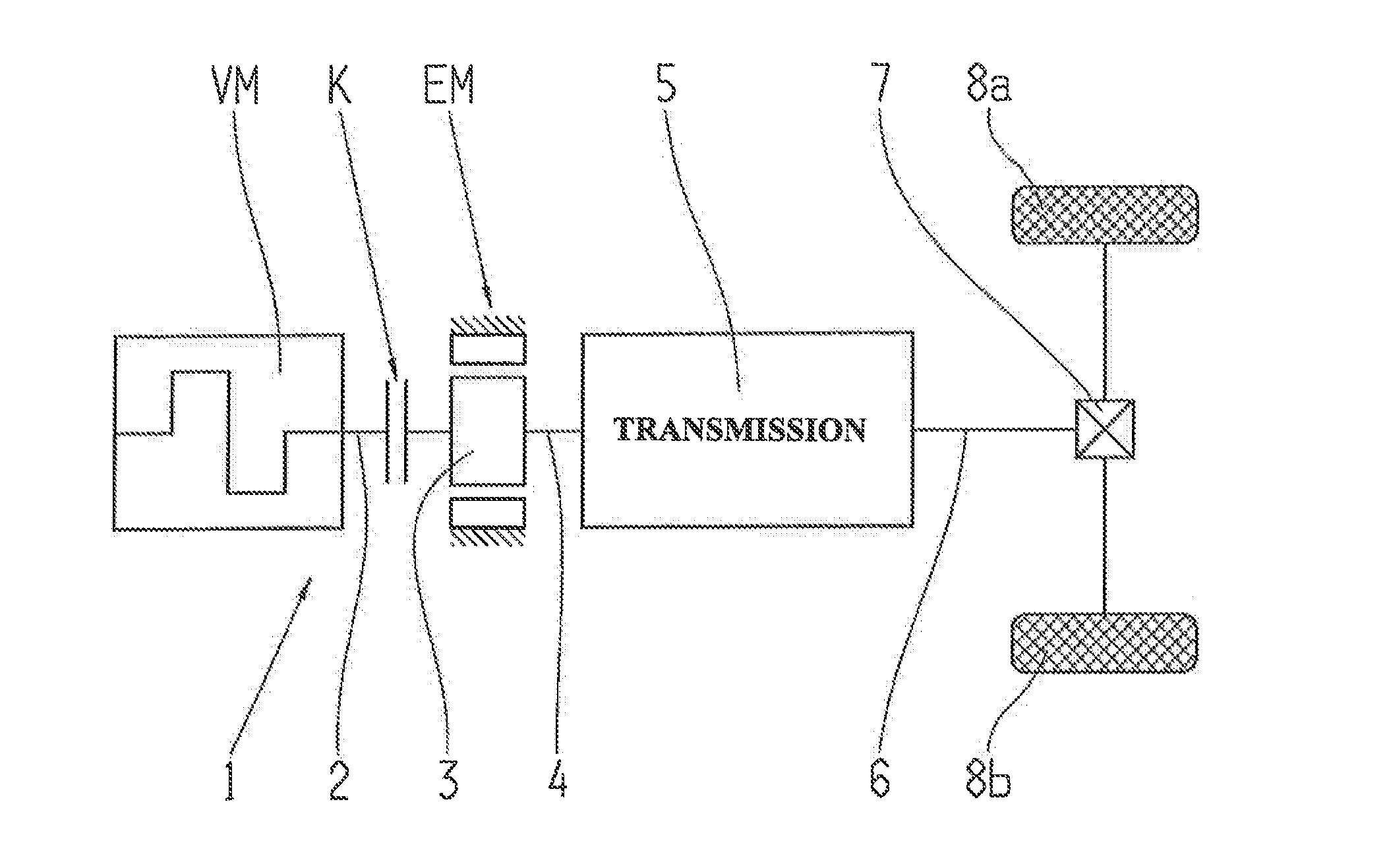
[0053]FIG. 3 illustrates, in schematic form, a parallel-action hybrid drive-train 1 of a motor vehicle, with which the control method according to the invention described below can be applied.

[0054]The hybrid drive-train 1 has an internal combustion engine VM with a driveshaft 2, an electric machine EM that can be operated at least as a motor with a rotor 3, and a transmission 5 with a transmission input shaft 4 and a transmission output shaft 6. The electric machine EM is arranged coaxially over the transmission input shaft 4 and in this case, as a example, the rotor 3 of the electric machine EM is connected in a rotationally fixed manner directly to the transmission input shaft 4. Alternatively, the rotor 3 of the electric machine EM could be drive-connected to the transmission input shaft 4 by way of a step-down transmission stage, so enabling a coaxial or axis-parallel arrangement of the electric machine EM relative to the transmission input shaft.

[0055]With the direct connectio...


PUM


Abstract

A method of controlling a hybrid drive-train of a vehicle having a combustion engine with a driveshaft, a transmission with an input shaft and an output shaft that drives a transfer box. An electric machine has a rotor that is connected to the transmission input shaft. A separator clutch is arranged between the engine driveshaft and the transmission input shaft. For coupling of the engine, the engine is first accelerated, with a rotational speed regulation, toward a target speed until a reference speed is reached or exceeded while the clutch remains disengaged, then, with continuous speed regulation, the engine is adjusted to a corrected target speed while the clutch is engaged until a target torque is obtained, then, with torque control, the engine is adjusted to the target torque while the clutch, with differential rotational speed regulation, is regulated to a target speed difference, and finally the clutch is engaged.

Description

[0001]This application is a National Stage completion of PCT / EP2012 / 061319 filed Jun. 14, 2012, which claims priority from German patent application serial no. 10 2011 079 079.9 filed Jul. 13, 2011.FIELD OF THE INVENTION[0002]The invention concerns a method for controlling a hybrid drive-train of a motor vehicle.BACKGROUND OF THE INVENTION[0003]Such a hybrid drive-train of a motor vehicle comprises an internal combustion engine with a driveshaft, an adjustable-ratio transmission with a transmission input shaft and a transmission output shaft in driving connection with an axle transmission or transfer box, an electric machine that can be operated at least as a motor having a rotor that is drive-connected to the transmission input shaft, and a separator clutch in the form of an automated friction clutch arranged between the driveshaft of the internal combustion engine and the transmission input shaft. With such a hybrid drive-train, starting from electrically powered driving operation...

Claims


Application Information

Patent Timeline
IPC IPC(8): B60W20/00
CPCY10S903/902B60W20/40B60K6/48B60W10/02B60W10/06B60W20/00B60W30/18027B60K2006/4825B60W2710/0666B60W2710/025B60W2710/027Y02T10/62B60W10/08B60W20/30
Inventor SCHOLZ, JAKOBZOLLNER, TOBIASBACHER, HOLGER
Owner ZF FRIEDRICHSHAFEN AG
Learn More