
Electron beam exposure apparatus and method

an exposure apparatus and electron beam technology, applied in the direction of instruments, magnetic discharge control, beam deviation/focusing by electric/magnetic means, etc., can solve the problem of electron beam blur, achieve fine patterns, suppress electron beam blur, and high accuracy

Inactive Publication Date: 2014-05-15
ADVANTEST CORP
View PDF4 Cites 0 Cited by
  • Summary
  • Abstract
  • Description
  • Claims
  • Application Information

AI Technical Summary

Benefits of technology

This patent describes an electron beam exposure apparatus that aims to improve the accuracy of patterning by minimizing blur in the electron beam. The apparatus achieves this by reducing the current density of the electron beam and using multiple beam shaping portions to remove the edge of the beam and suppress blur. The technical effect is the ability to create fine patterns with high accuracy.

Problems solved by technology

However, increasing the area irradiated with an electron beam and the current density thereof can increase the influence of the coulomb interaction between electrons in the electron beam, thus causing a blur of the electron beam.

Method used


Image

  • Electron beam exposure apparatus and method
  • Electron beam exposure apparatus and method
  • Electron beam exposure apparatus and method

Examples


first embodiment

[0057]FIG. 7 is a block diagram of an electron beam exposure apparatus according to a first embodiment. FIG. 8 is a view illustrating a beam shaping section of the electron beam exposure apparatus of FIG. 7. FIGS. 9A to 9D are views illustrating a method of shaping an electron beam in the beam shaping section of FIG. 8.

[0058]As illustrated in FIG. 7, an electron beam exposure apparatus 100 according to the first embodiment includes an integrated control system 21, an exposure data memory 23, a control section 31, an electron optical system column 80, and a sample chamber 71. The electron optical system column 80 includes a beam shaping section 80a and a substrate deflection section 80b, and the inside thereof has reduced pressure.

[0059]As illustrated in FIG. 8, the beam shaping section 80a includes an electron gun 101 configured to emit an electron beam EB0 and a first beam shaping portion 103 below the electron gun 101 (on the downstream side of the electron beam). The first beam s...

second embodiment

[0117]FIG. 11 is a block diagram of an electron beam exposure apparatus according to a second embodiment.

[0118]An electron beam exposure apparatus 200 according to the second embodiment differs from the VSB-type electron beam exposure apparatus 100 illustrated in FIG. 7 in terms of being capable of performing the CP-type electron beam exposure. The same structures of the electron beam exposure apparatus 200 of the second embodiment as those of the electron beam exposure apparatus 100 illustrated in FIGS. 7 and 8 are given the same referential numerals, and the detailed description thereof is omitted.

[0119]As illustrated in FIG. 11, in the electron beam exposure apparatus 200 according to the second embodiment, a beam shaping section 81a of a column cell 81 includes a first beam shaping portion 103, a first deflector 104, a second beam shaping portion 140, and electromagnetic lenses 105 and 107.

[0120]The beam shaping section 81a includes a CP mask 110 having a plurality of opening pa...


PUM


Abstract

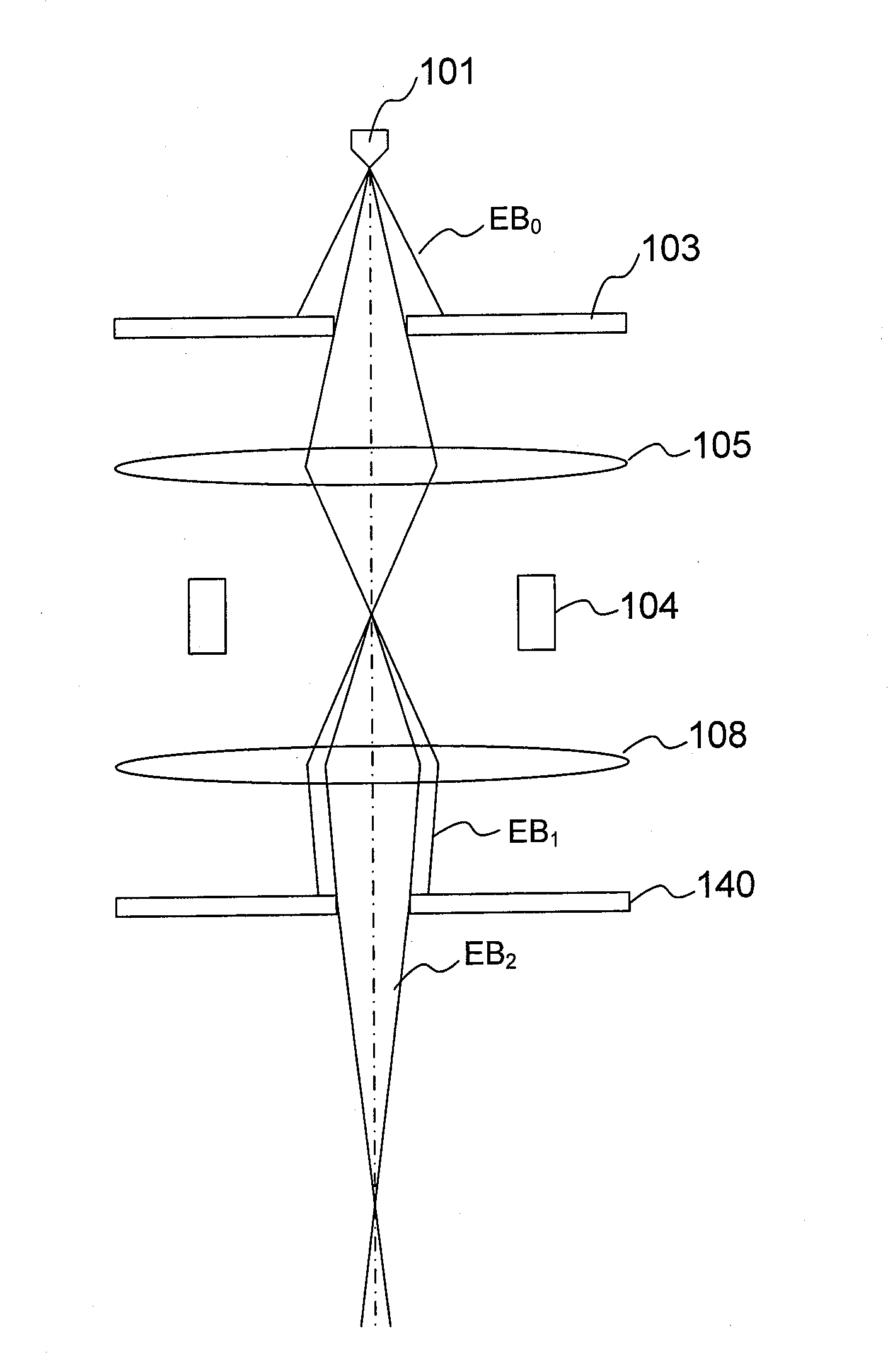
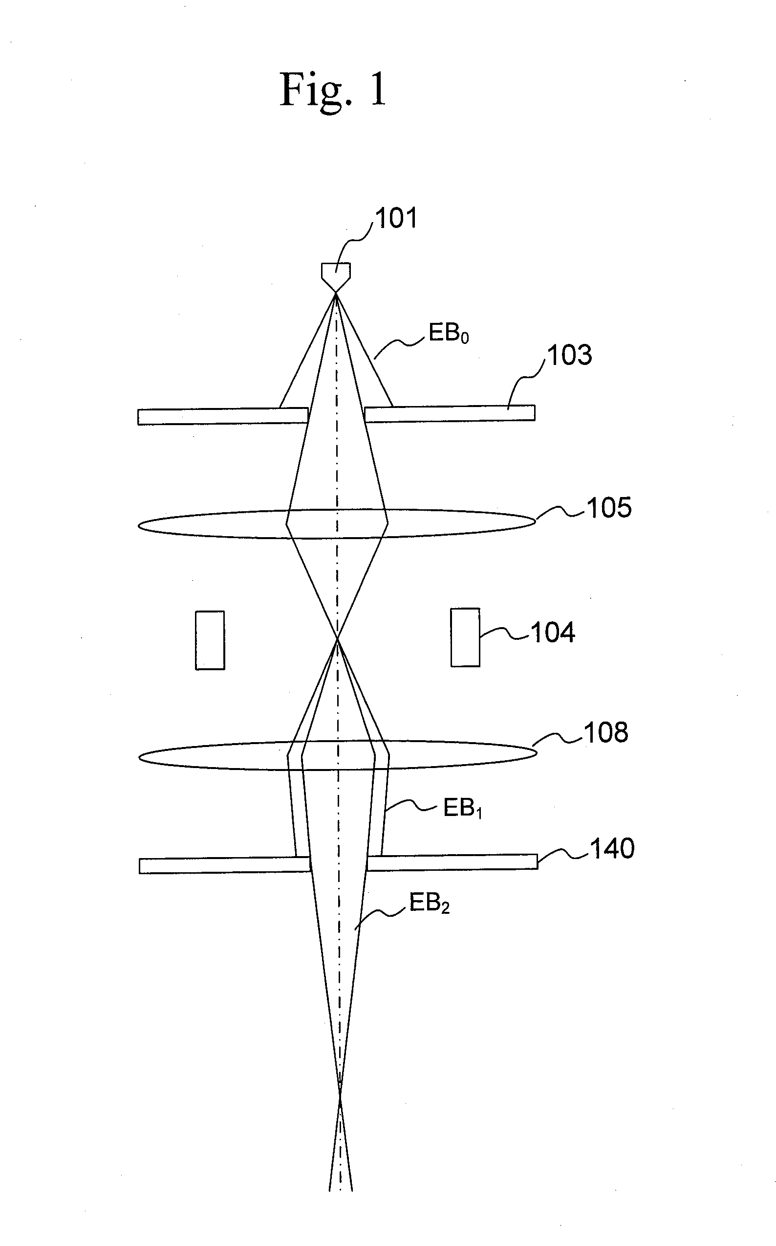
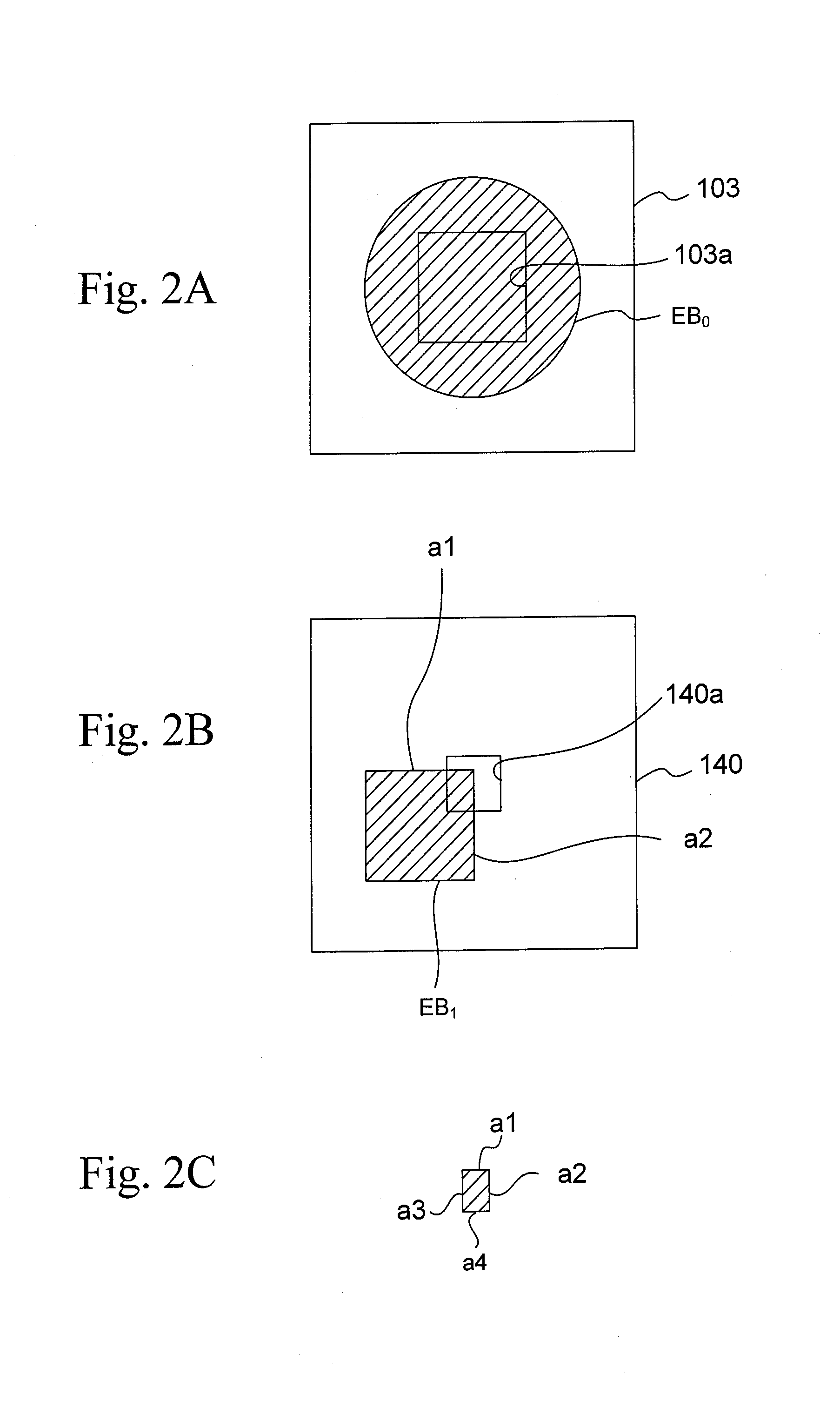
An electron beam EB0 emitted from an electron gun 101 is cut by a first aperture 103a into a rectangular electron beam DB', which is then cut by second and third apertures 140a, 150a into an electron beam EB3 so that the edge cut by the first aperture 103a is removed from the electron beam EB1. This can prevent blur due to the influence of coulomb interaction of the electron beam EB1 between the first and second apertures 103a to 140a and perform highly accurate exposure with the electron beam EB3 having high current density.

Description

CROSS-REFERENCE TO RELATED APPLICATIONS[0001]This application is based upon and claims the benefit of priority of the prior Japanese Patent Application No. 2012-247696, filed on Nov. 9, 2012, the entire contents of which are incorporated herein by reference.TECHNICAL FIELD[0002]The present invention relates to an electron beam exposure apparatus and an electron beam exposure method.BACKGROUND ART[0003]Methods for exposing a pattern with electron beams include variable shaped beam (VSB) methods and character projection (CP) methods.[0004]These exposure methods cut an electron beam emitted from an electron gun with a beam shaping section including a rectangular opening and further cut off a part of the cut electron beam with another beam shaping section to provide electron beams shaped into various profiles. The shaped electron beam is then reduced by 20- to 50-fold with an electron lens system and is then projected onto an exposure object.[0005]In order to increase the throughput of ...

Claims


Application Information

Patent Timeline
Patent Type & Authority Applications(United States)
IPC IPC(8): H01J37/317
CPCH01J37/3174H01J37/04H01J2237/04H01J2237/045H01J2237/1538H01J2237/31776B82Y10/00B82Y40/00
Inventor YAMADA, AKIO
Owner ADVANTEST CORP
Learn More