
NFC device and communication method

Active Publication Date: 2014-05-08
NXP BV
View PDF4 Cites 44 Cited by
  • Summary
  • Abstract
  • Description
  • Claims
  • Application Information

AI Technical Summary

Benefits of technology

The invention describes a detuning circuit for an antenna unit. The detuning circuit includes several components such as capacitors, transistors, and resistors. The circuit is designed to enable short-circuiting of the antenna unit's coil when requested by a processing unit. The technical effect of this design is improved efficiency and control over the antenna unit's detuning process.

Problems solved by technology

However, creating electrical connections between the cover and the mobile phone is cumbersome and expensive.

Method used


Image

  • NFC device and communication method
  • NFC device and communication method
  • NFC device and communication method

Examples


Embodiment Construction

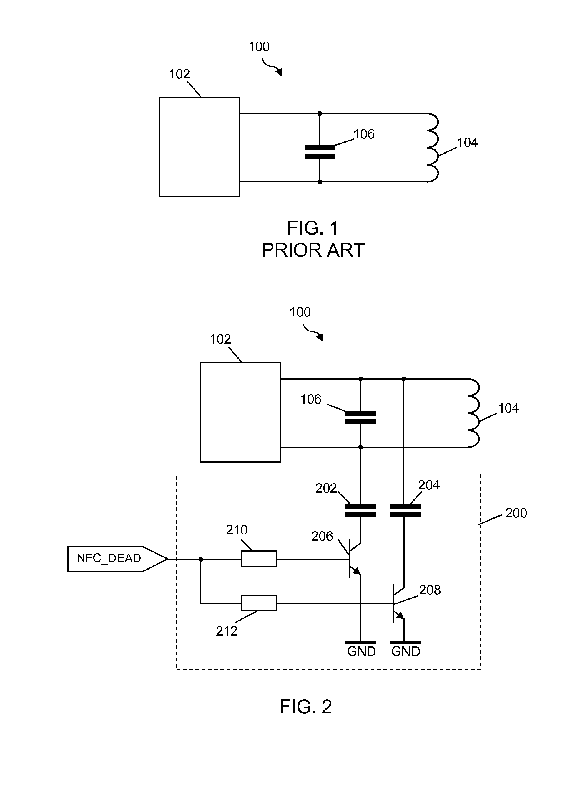
[0018]FIG. 1 shows a portion of a conventional NFC device. The NFC device 100 comprises an NFC integrated circuit 102, an antenna unit 104 and a tuning capacitance 106. The tuning capacitance 106 is relatively small and it is used to tune the coil of the antenna unit exactly to an operating frequency of 13.56 MHz.

[0019]FIG. 2 shows a portion of an NFC device according to an exemplary embodiment of the invention. The NFC device 100 according to this exemplary embodiment has been extended with a detuning circuit 200. The detuning circuit 200 is arranged to cause a periodic detuning of the antenna unit 104 under control of a detuning signal NFC DEAD.

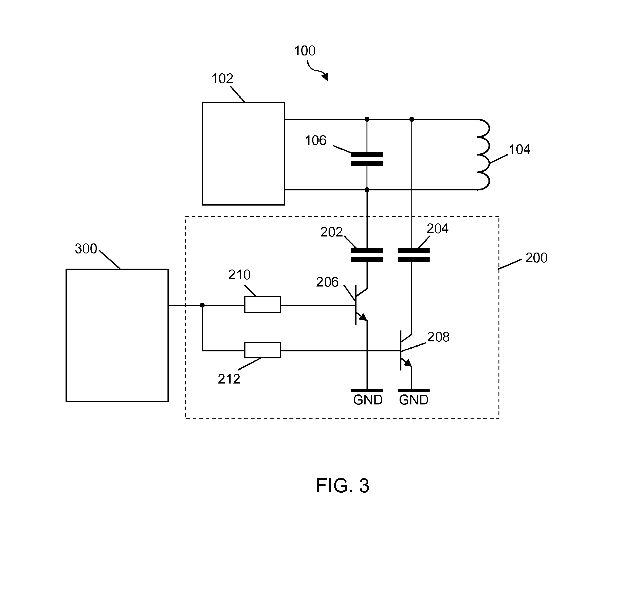
[0020]The detuning circuit 200 comprises a first capacitor 202 connected to the tuning capacitance 106 of the NFC device 100 and to a first input of the antenna unit 104, a second capacitor 204 connected to a second input of the antenna unit 104, a first transistor 206 connected to the first capacitor 202 and to ground GND, a second transis...


PUM


Abstract

According to an aspect of the invention, an NFC device for communicating with an NFC reader is conceived, the NFC device comprising an NFC integrated circuit, an antenna unit connected to said NFC integrated circuit, and a detuning circuit, wherein the detuning circuit is arranged to cause a periodic detuning of the antenna unit to a detuned state, such that data transmission between the NFC device and the NFC reader may take place periodically while the NFC device and the NFC reader remain within communication range of each other.

Description

FIELD OF THE INVENTION[0001]The invention relates to an NFC device for communicating with an NFC reader. The invention also relates to a cover comprising an NFC device. The invention further relates to a method of communication between an NFC device and an NFC reader.BACKGROUND OF THE INVENTION[0002]NFC-enabled mobile phones have become increasingly popular. Also, phone sleeves or covers for such mobile phones have entered the market. These covers can be equipped with integrated sensors which are able to measure physical phenomena, such as temperature, humidity and pressure. The sensors produce measurement results that are sent from the cover to the mobile device, which is typically done via electrical connections between the cover and the mobile phone. For example, this can be done via a docking plug of the mobile phone. Subsequently, the measurement results can be processed by the mobile phone. However, creating electrical connections between the cover and the mobile phone is cumb...

Claims


Application Information

Patent Timeline
IPC IPC(8): H04B5/00
CPCH04B5/0056G06K7/0008G06K7/10148G06K7/10237G06K19/0723H04B5/77
Inventor HENDRICKSEN, RUUDMOONEN, OSWALD
Owner NXP BV
Learn More