Method of controlling an aircraft electrical power generation system
- Summary
- Abstract
- Description
- Claims
- Application Information
AI Technical Summary
Benefits of technology
Problems solved by technology
Method used
Image
Examples
Embodiment Construction
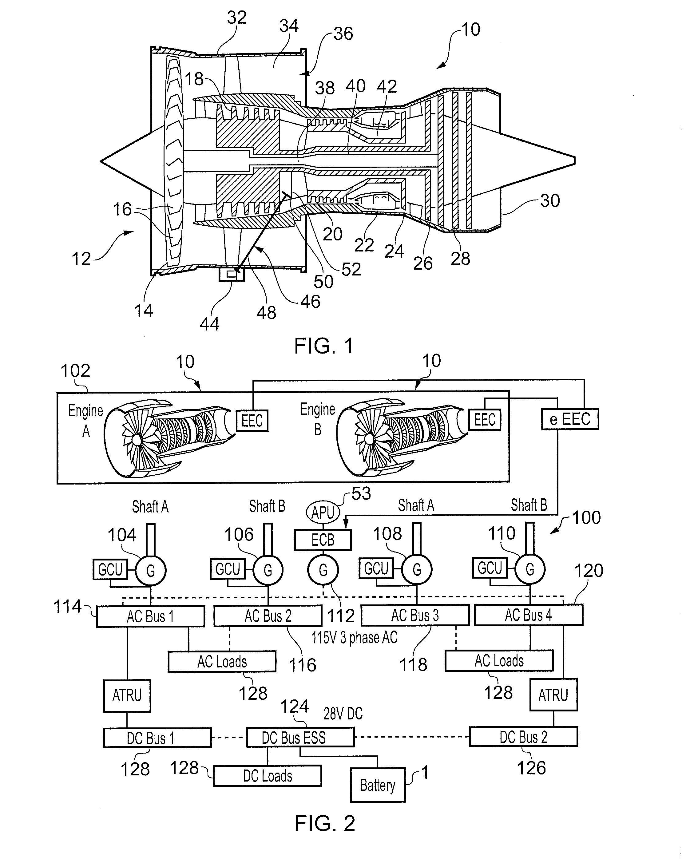
[0046]FIG. 1 shows a conventional ducted fan gas turbine engine 10 comprising, in axial flow series: an air intake 12, a propulsive fan 14 having a plurality of fan blades 16, an intermediate pressure compressor 18, a high-pressure compressor 20, a combustor 22, a high-pressure turbine 24, an intermediate pressure turbine 26, a low-pressure turbine 28 and a core exhaust nozzle 30. A nacelle 32 generally surrounds the engine 10 and defines the intake 12, a bypass duct 34 and a bypass exhaust nozzle 36.
[0047]Air entering the intake 12 is accelerated by the fan 14 to produce a bypass flow and a core flow. The bypass flow travels down the bypass duct 34 and exits the bypass exhaust nozzle 36 to provide the majority of the propulsive thrust produced by the engine 10. The core flow enters the intermediate pressure compressor 18, high pressure compressor 20 and the combustor 22, where fuel is added to the compressed air and the mixture burnt. The hot combustion products expand through and ...
PUM
 Abstract
Description
Claims
Application Information
 - R&D
- Intellectual Property
- Life Sciences
- Materials
- Tech Scout
- Unparalleled Data Quality
- Higher Quality Content
- 60% Fewer Hallucinations
Browse by: Latest US Patents, China's latest patents, Technical Efficacy Thesaurus, Application Domain, Technology Topic, Popular Technical Reports.
© 2025 PatSnap. All rights reserved.Legal|Privacy policy|Modern Slavery Act Transparency Statement|Sitemap|About US| Contact US: help@patsnap.com


