
System and method for routing digital audio data using highly stable clocks

a technology of digital audio data and clocks, applied in the field of audio routing systems and networks, can solve the problems of unfavorable sharing a timing signal, clocks that “tick” at different rates, and their resonating frequency may change, and achieve the effect of high quality

Active Publication Date: 2014-05-01
WHEATSTONE CORP
View PDF10 Cites 6 Cited by
  • Summary
  • Abstract
  • Description
  • Claims
  • Application Information

AI Technical Summary

Benefits of technology

The present invention aims to provide a better method and device for transferring high-quality digital audio information without requiring clocking information, a self-clocking data stream, or the introduction of packet arrival timing. It also aims to prevent buffer overflow or underflow when transferring large real-time data.

Problems solved by technology

While the best quartz resonators can achieve an accuracy of one second in 10 years, they are sensitive to changes in temperature and acceleration and their resonating frequency may change as they age.
The problem with maintaining a concept of time occurs when multiple entities expect each other to have the same idea of what the time is.
Computers have the same problem: a quartz crystal on one computer will oscillate at a slightly different frequency than on another computer, causing the clocks to “tick” at different rates.
Sharing a common timing signal becomes unfeasible when the distance between devices increase or devices frequently change location.
Even at moderate distances, e.g., 50 meters, a common timing signal may require significant costs for cabling and configuration.
Additionally, even the smallest errors in keeping time can significantly add up over a long period.
Thus, transmission distances will add complexity and error to the system.
In general, the larger the number of hops between a computer and the original time source, the larger the error in synchronization will be.
Jitter is delay that varies over time.
Delays are caused by distance, errors and error recovery, congestion, the processing capabilities of systems involved in the transmission, and other factors.
Even if hardware-type delays are removed, the system would still have the speed-of-light delay.
It takes nearly 30 ms to send a bit through a cross-country fiber-optic cable, a delay that cannot be eliminated.
Delays of distance (called propagation delays) are especially critical when transmitting data to other countries (especially when considering all the equipment along the way that adds delay).
If the processing does not respect the AV-sync error, it will increase whenever data gets lost because of transmission errors or because of missing or mis-timed processing.
Disadvantages of timestamp-based syncing are based on the fact that time is a relative concept to the observer, and different machine clocks can be out of sync.
The latter being very difficult to implement.
Timestamp based syncing works for client-to-master syncing but does not work as well for peer-to-peer syncing or where syncing can occur with two masters.
This method is vulnerable to a single point of failure, based on whatever generates the timestamp.
On systems where clock information cannot be directly transferred, the clocking information can often be inferred from the arrival time of the data but not very accurately.
This is especially true for systems using Ethernet or similar data networks, where traffic from other sources can potentially interfere with accurate packet timing.
Even in cases where other traffic is not a problem, there is usually enough uncertainty in the transmission and arrival time of packets to cause the derived clock on the receive side to suffer from some jitter.
The prior art has attempted to solve the time synchronization problems through the introduction of a single atomic clock, which unfortunately has led to the problems associated with a GPS time synchronization system.
However, the patent does not disclose the use of multiple clocks (or more accurately, multiple highly accurate clocks, such as atomic clocks) at the transmitter and receiver that would run simultaneously to reduce buffer size, eliminate the requirements of clock resynchronization, data rate control, buffer management, or any combination thereof
This is because the source clock cannot be adjusted to match the multiple destinations which have varying clock rates.
Basically, there is not enough data in the buffer, and eventually all the data packets get used.
Alternatively, if the destination is not using the data packets fast enough, the buffer will overflow, that is, there is not enough storage space, and the system must continue to put data in as long as the data is being received.
If the system is not using data at exactly the same rate as the incoming data rate, the data packets build up and eventually overflow the buffer.
Buffer underflow and overflow conditions are indicative of a common problem in synchronization.
One structural solution is to employ very large buffers; however, that requires predetermined knowledge of the amount of usage expected in a given transmission period.

Method used


Image

  • System and method for routing digital audio data using highly stable clocks
  • System and method for routing digital audio data using highly stable clocks
  • System and method for routing digital audio data using highly stable clocks

Examples


Embodiment Construction

)

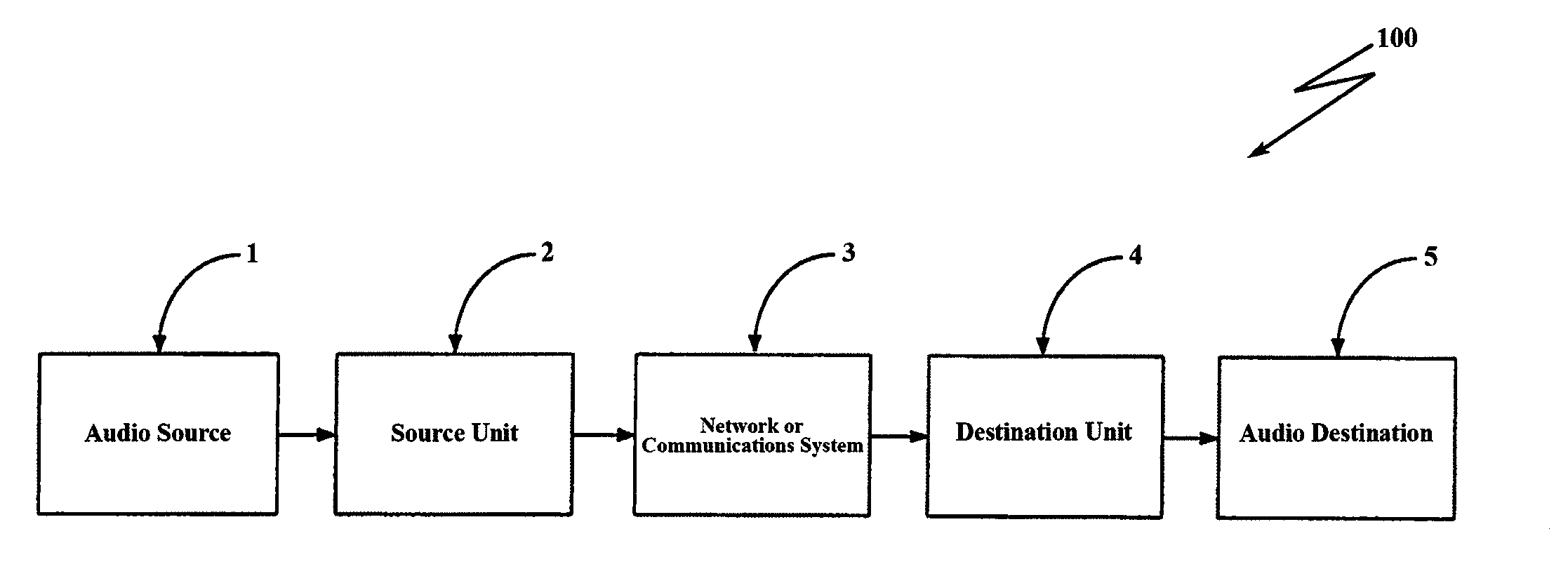
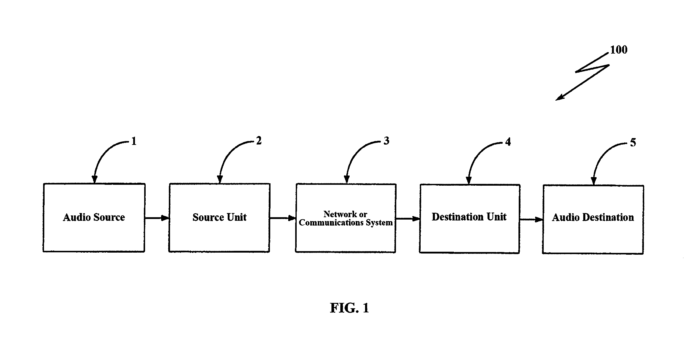
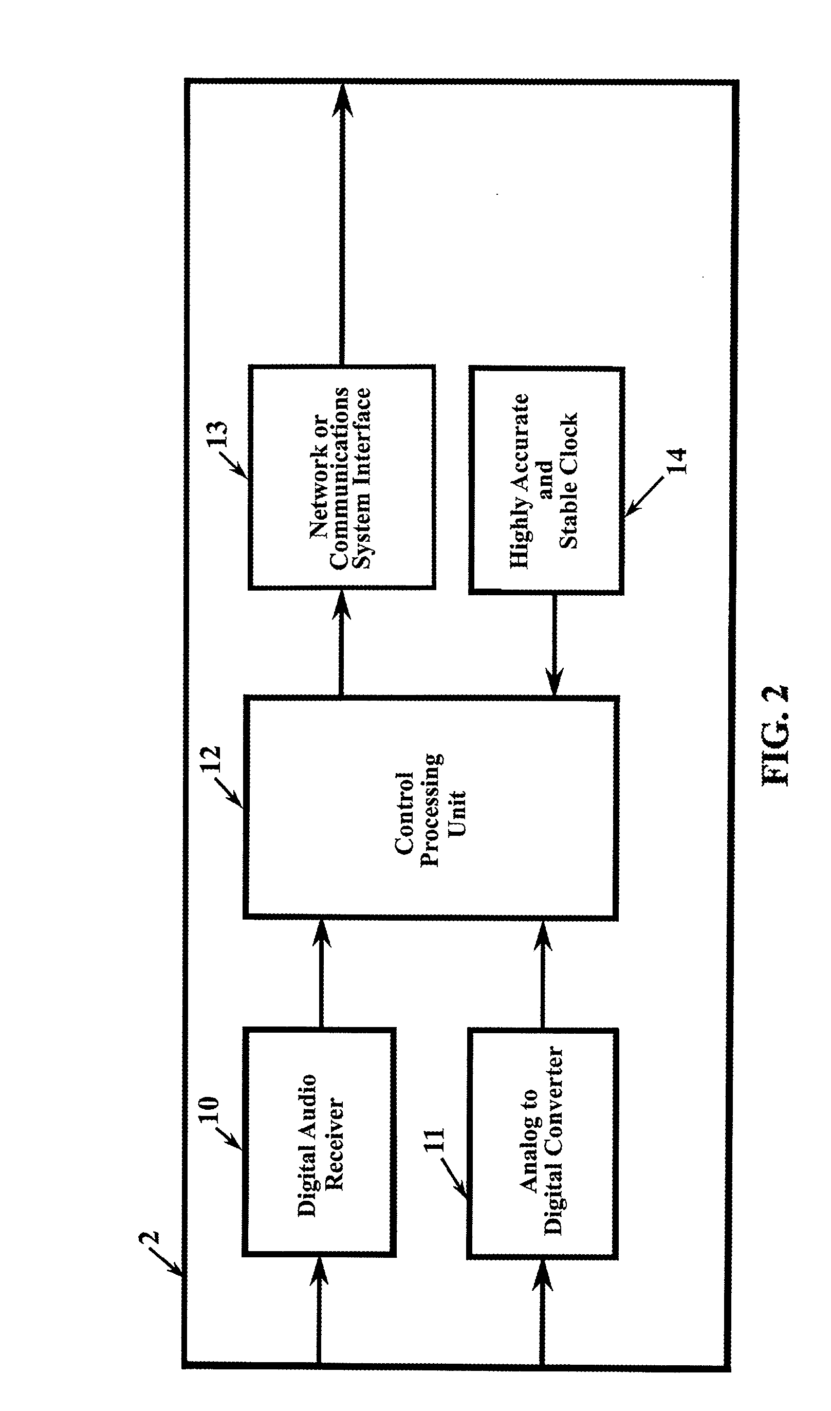
[0042]In describing the preferred embodiment of the present invention, reference will be made herein to FIGS. 1-4 of the drawings in which like numerals refer to like features of the invention.

[0043]The present invention involves equipment to transfer digital data, typically musical or sound of some sort, while eliminating even very slight offsets in the rate at which the digital signals are received. Preferably, each data packet is audible, and the object is to minimize the variation in that rate when sending a digital data either from one source to a plurality of receiving destinations or from a plurality of sources to be combined at a single destination, such that complete synchronization is always achieved.

[0044]A digital audio transfer apparatus is presented, which will allow for an improved method for transferring digital data in real time with low latency. In this manner, the destination begins to play immediately after the source begins to send. Importantly, independent, hi...


PUM


Abstract

A system and method for routing digital audio data synchronized where the source and destination units are synchronized to individual, local chip-scale atomic clocks. A source unit receives audio data and digitizes the data in synchronization to a local atomic clock. The data is transmitted via a communications network to at least one destination unit that receives the network transmitted data, decodes and reconstructs the data in synchronization with its own local atomic clock, and outputs the data to an audio destination.

Description

BACKGROUND OF THE INVENTION[0001]1. Field of the Invention[0002]This invention relates to audio routing systems and networks, and in particular to a system and method for transferring data over audio and video networks real-time using highly accurate and stable clocks to control the transfer, digitization, and playback processes.[0003]2. Description of Related Art[0004]Many systems are available to provide high quality digital and audio data transfer from one device to another over a digital network. Transferring audio data in real-time requires that the source and destination generate and consume the data at identical rates in order to avoid accumulating data or running out of data at the destination. This requires some form of clock synchronization.[0005]Clock synchronization deals with understanding the temporal ordering of events produced by concurrent processes. It is useful for synchronizing senders and receivers of messages, controlling joint activity, and the serializing con...

Claims


Application Information

Patent Timeline
IPC IPC(8): G06F17/00
CPCH04N21/242H04N21/20H04N21/4305G06F17/00
Inventor SNOW, GARY, C.
Owner WHEATSTONE CORP
Learn More