
Inverter control method and system for eco-friendly vehicle

Active Publication Date: 2014-04-17
HYUNDAI MOTOR CO LTD
View PDF3 Cites 7 Cited by
  • Summary
  • Abstract
  • Description
  • Claims
  • Application Information

AI Technical Summary

Benefits of technology

The present invention provides an inverter control system and method for an eco-friendly vehicle that improves switching loss, electromagnetic performance, NVH performance, control stability, and overall operational performance compared to conventional methods that use one fixed switching frequency and one fixed sampling frequency across the entire operation area.

Problems solved by technology

The motor system, which typically includes a motor, which is operated as a driving source for an eco-friendly vehicle, and an inverter, has several problems associated therewith such as a noise occurring during driving operation / regenerating operation, efficiency degradation caused by switching loss, electromagnetic performance degradation, and so forth.
However, a significant amount of noise is generated.
When the base switching frequency is set to be high over the entire operational area to reduce the inverter's noise (for example, the base switching frequency is fixed to 8 kHz), NVH performance becomes better (i.e., pulse width modulation (PWM) current ripple is reduced), but electromagnetic performance is deteriorated and switching loss increases (i.e., leading to degradation of heel hold performance in vehicle constraint conditions), such that inverter efficiency and fuel efficiency are degraded as well.
As to electromagnetic performance, as the switching frequency increases, radiated electromagnetic noise increases (e.g., as a result, for example, AM radio reception becomes poor); as the switching frequency decreases, radiated noise decreases and thus electromagnetic performance becomes better.
However, in a conventional case, one switching frequency is fixed and used over the entire operation area without any consideration of a motor driving conditions or the like (that is, a fixed frequency scheme is used), resulting in high switching loss caused by heat emission of a switching element and in weakness of electromagnetic performance.
Moreover, when a sampling frequency is high, although inverter control stability becomes better, a load on a processor executing the control increases because the processor has to obtain control parameters such as sensing current, motor angular information, etc., in a shorter period of time and calculate a larger number of control values the processor may become overloaded.
That is, in a conventional system, as the switching frequency is set and fixed at a high rate over the entire operational area, there are apparent disadvantages such as electromagnetic performance degradation and switching loss increase as well as some advantages.

Method used


Image

  • Inverter control method and system for eco-friendly vehicle
  • Inverter control method and system for eco-friendly vehicle
  • Inverter control method and system for eco-friendly vehicle

Examples


first embodiment

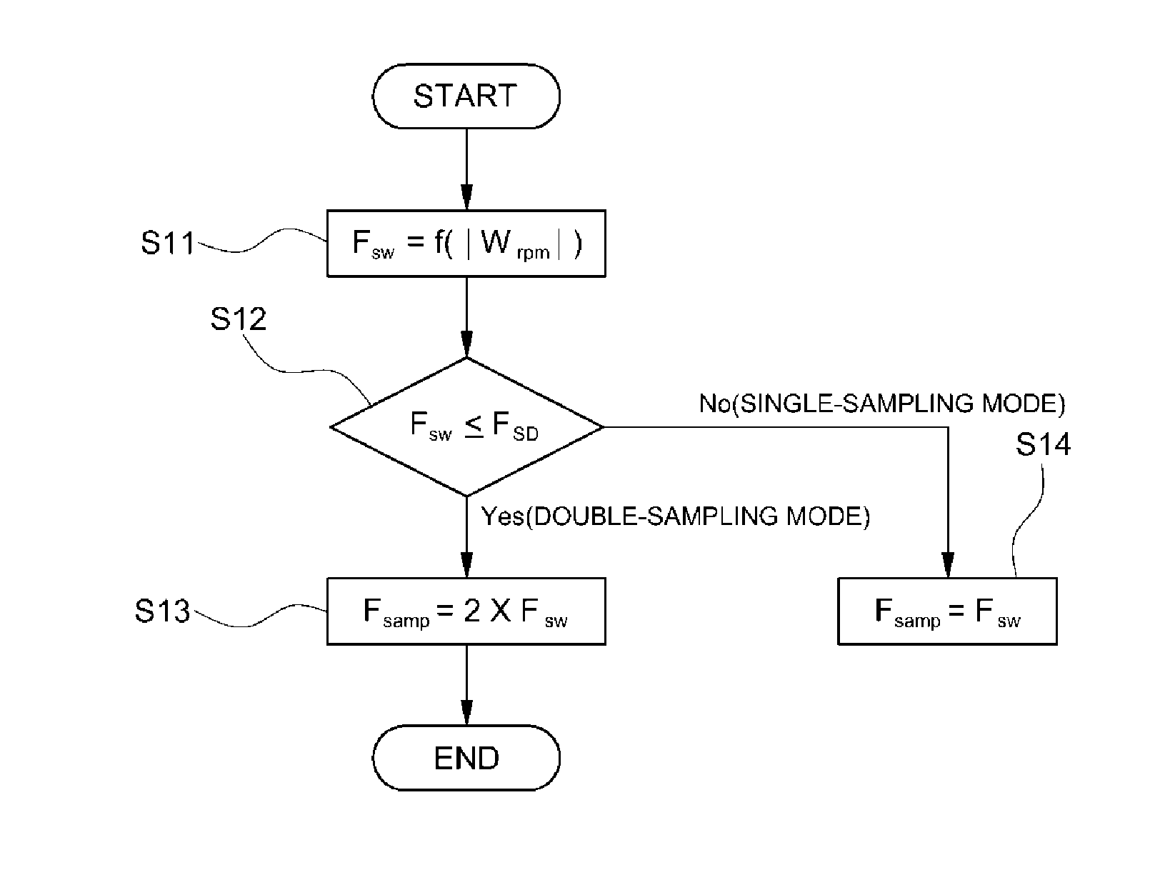
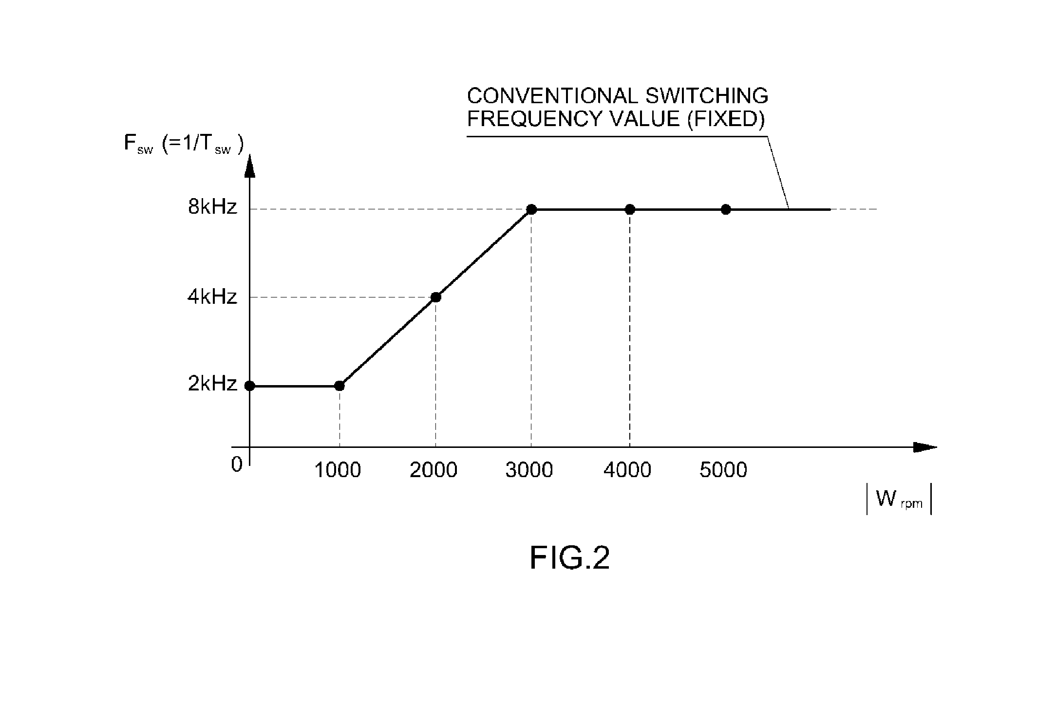
[0043]FIG. 1 is a flowchart of an inverter control method according to a first exemplary embodiment of the present invention, and FIG. 2 is a diagram showing a state where a switching frequency Fsw is variable-controlled (continuous-variable-controlled) in an inverter control method according to the present invention.

[0044]In FIG. 2, a conventional fixed switching frequency (e.g., about 8 kHz) is also shown.

[0045]FIG. 3 is a diagram showing a transition scheme of a sampling frequency Ksamp in an inverter control method according to the first exemplary embodiment of the present invention, in which the sampling frequency Fsamp changes with the switching frequency Fsw and to transition (single sampling double sampling) is performed in a particular condition.

[0046]In first exemplary embodiment of the present invention, an inverter switching frequency may be variable-controlled according to a vehicle's driving condition, and a sampling frequency may be properly controlled according to th...

second embodiment

[0077]The second exemplary embodiment further provides sophisticatedly segmented control logic in which the controller determines whether the current motor operation state is in a driving operation state or a regenerating operation state and the switching frequency Fsw and the sampling frequency Fsamp are determined from the base switching frequency Fsw—base separately for the driving operation state and the regenerating operation state. In addition, in the second embodiment, it is determined whether to conduct step transition of the switching frequency and one of the single-sampling mode and the double-sampling mode is selected, according to the current inverter input voltage, motor speed, torque command, or inverter power.

[0078]That is, when the motor is in the driving operation state, when three conditions all are satisfied: i.) an inverter input voltage VDC is greater than a preset first reference voltage VDC_cal1; ii.) the motor speed Wrpm (e.g., an absolute value thereof) is a...

third embodiment

[0105]With reference to FIG. 8, a description will be made below regarding a process of performing transition between single sampling and double sampling based on a motor speed in the inverter control method according to the present invention.

[0106]First, the controller monitors the current motor speed Wrpm and variable-controls the inverter switching frequency Fsw—nom according to the current motor speed Wrpm. The switching frequency Fsw—nom is obtained by summing the base switching frequency Fsw—base and the spread frequency Fsw—inj as stated above, and both the base switching frequency Fsw—base and the spread frequency Fsw—inj are calculated as values changing with the motor speed Wrpm, such that when the motor speed Wrpm changes, the switching frequency Fsw—nom also changes correspondingly.

[0107]Referring to FIG. 8, in step S11 where the switching frequency Fsw—nom is calculated as a value corresponding to the motor speed Wrpm, the switching frequency Fsw—nom is determined as a ...


PUM


Abstract

Provided is an inverter control system and method for an eco-friendly vehicle, by which overall improvements can be obtained in terms of switching loss, electromagnetic performance, noise-vibration-harshness (NVH) performance, control stability, and so forth, when compared to a conventional case in which one fixed switching frequency and one fixed sampling frequency are used over the entire operation area. To this end, the inverter control method for an eco-friendly vehicle which generates a pulse width modulation (PWM) signal according to a switching frequency and a sampling frequency and controls ON / OFF driving of a switching element, in which a controller changes and sets the switching frequency according to a current motor speed, changes and sets a sampling frequency according to the switching frequency, and controls on / off driving of a switching element according to the switching frequency corresponding to the motor speed and the sampling frequency.

Description

CROSS-REFERENCE TO RELATED APPLICATION[0001]This application claims under 35 U.S.C. §119(a) the benefit of Korean Patent Application No. 10-2012-0115174 filed on Oct. 17, 2012 and Korean Patent Application Publication No. 10-2013-0050340 filed May 3, 2013, the entire contents of which are incorporated herein by reference and is a continuation in part of U.S. patent application Ser. No. 13 / 717,238, filed on Dec. 17, 2012.BACKGROUND[0002](a) Technical Field[0003]The present invention relates to an inverter control method and system for an eco-friendly vehicle, and more particularly, to an inverter control method and system for an eco-friendly vehicle, by which overall improvements can be made in terms of switching loss, electromagnetic performance, noise-vibration-harshness (NVH) performance, control stability, etc., when compared to a conventional control methods in which one fixed switching frequency and one fixed sampling frequency are used over the entire operation area.[0004](b) ...

Claims


Application Information

Patent Timeline
IPC IPC(8): H02P6/00
CPCH02P6/002H02P6/001H02M7/537H02M2001/0003H02P27/085H02M1/0003
Inventor BAE, SU HYUNCHOI, WON KYOUNGKIM, SUNG KYUKWAK, MU SHIN
Owner HYUNDAI MOTOR CO LTD
Learn More