
Electrical contact component

a technology of electrical contact and component, applied in the direction of coupling contact member, coupling device connection, liquid/solution decomposition chemical coating, etc., can solve the problems of low contact reliability, complicated process management, disadvantageous increase in the cost of electrical contact component, etc., and achieve excellent contact reliability

Inactive Publication Date: 2014-04-03
PANASONIC CORP
View PDF13 Cites 14 Cited by
  • Summary
  • Abstract
  • Description
  • Claims
  • Application Information

AI Technical Summary

Benefits of technology

The present invention provides an electrical contact component that has excellent contact reliability and mountability. This is achieved by selectively forming a plating layer containing carbon nanotubes or carbon blacks on the surface of the contact point part for better contact reliability, and a plating layer with higher solder wettability than that containing carbon nanotubes or carbon blacks on the mounting part for better mountability. The surface of the contact component also has an amorphous plating layer with a nanocarbon material exposed from it, which exhibits excellent contact reliability and corrosion resistance and is cost-effective to manufacture.

Problems solved by technology

However, since the noble metal is expensive, the cost of the electrical contact component is disadvantageously increased when the noble metal is used in large quantity.
Since oxide which is apt to block an electric connection is formed on the surface of the contact point part after reflow, contact resistance in a low contact pressure region (a contact power of 9.8×10⁻³ N (1 gf) or less when a gold alloy-based plating layer is formed on the surface of the contact point part) is increased, which disadvantageously causes low contact reliability.
However, this disadvantageously causes complicated process management.
Furthermore, when the sealing treatment is performed, an insulating oily component is used as a lubrication component, which disadvantageously deteriorates the contact reliability.

Method used


Image

  • Electrical contact component
  • Electrical contact component
  • Electrical contact component

Examples


first embodiment

[0048]Hereinafter, a first embodiment of the present invention will be described.

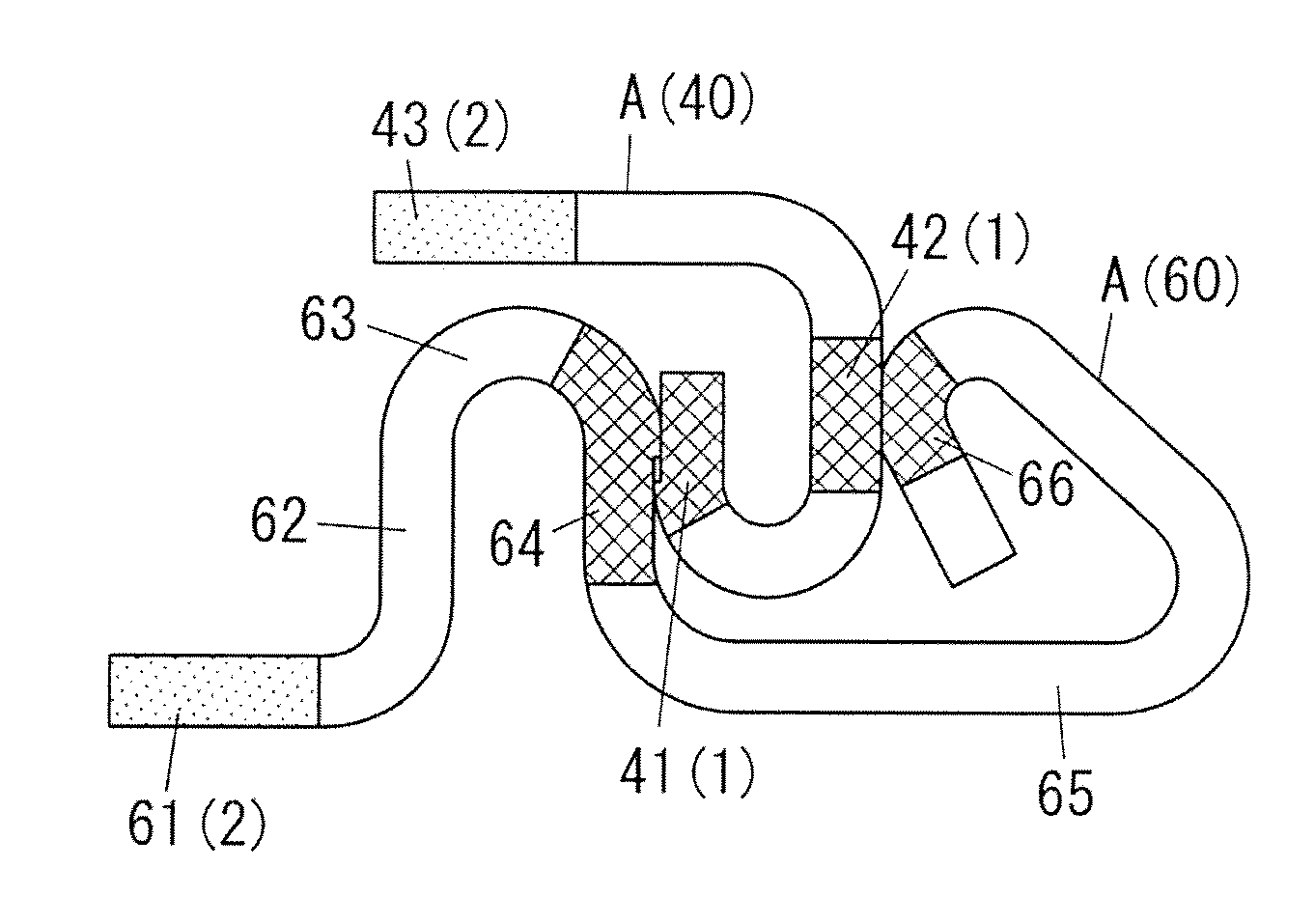
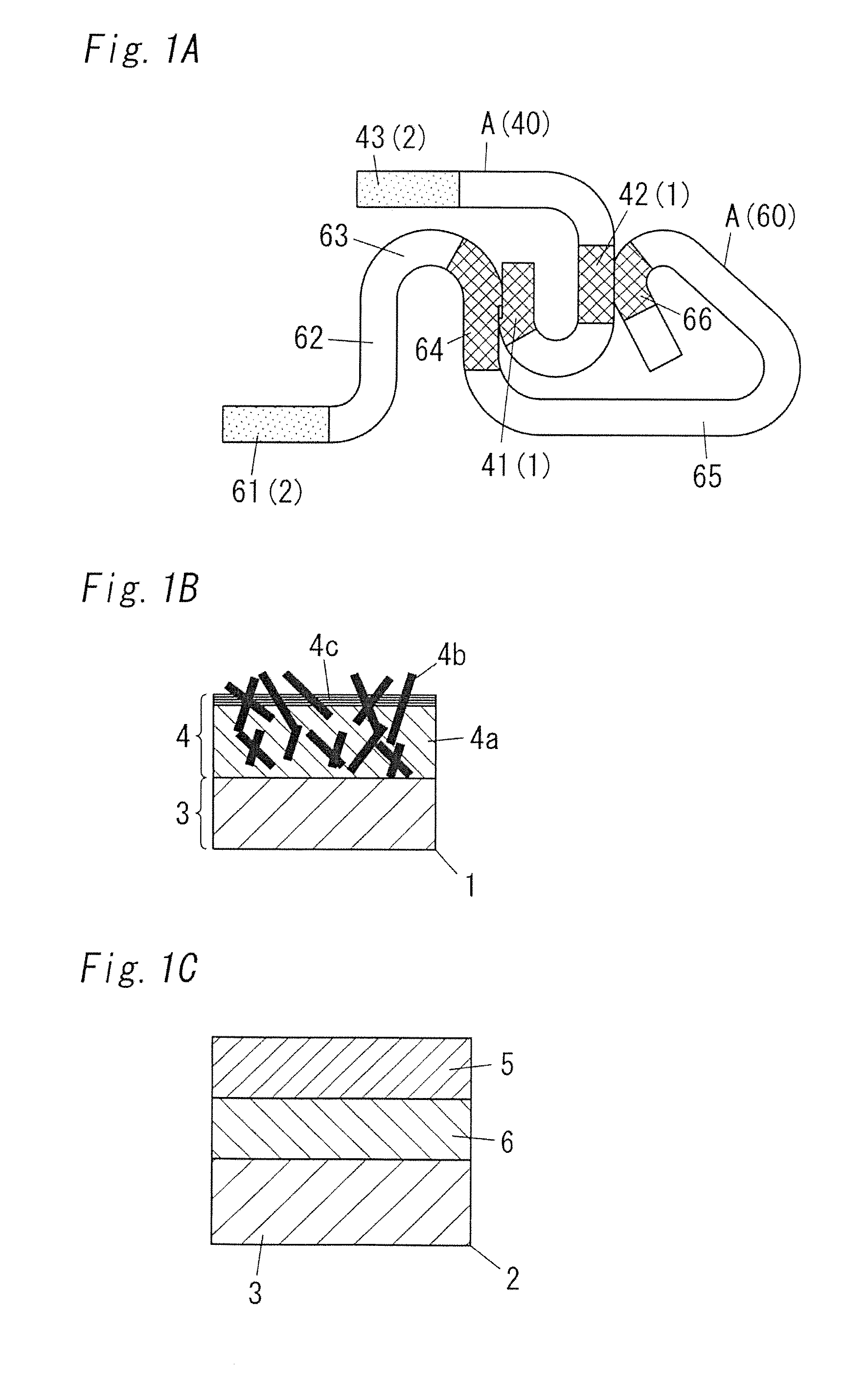
[0049]An electrical contact component A is used as a terminal part of a connector, a moving contact point such as a switch or a relay, and a fixed contact point or the like. In particular, the electrical contact component A is suitably used in a low contact pressure region.

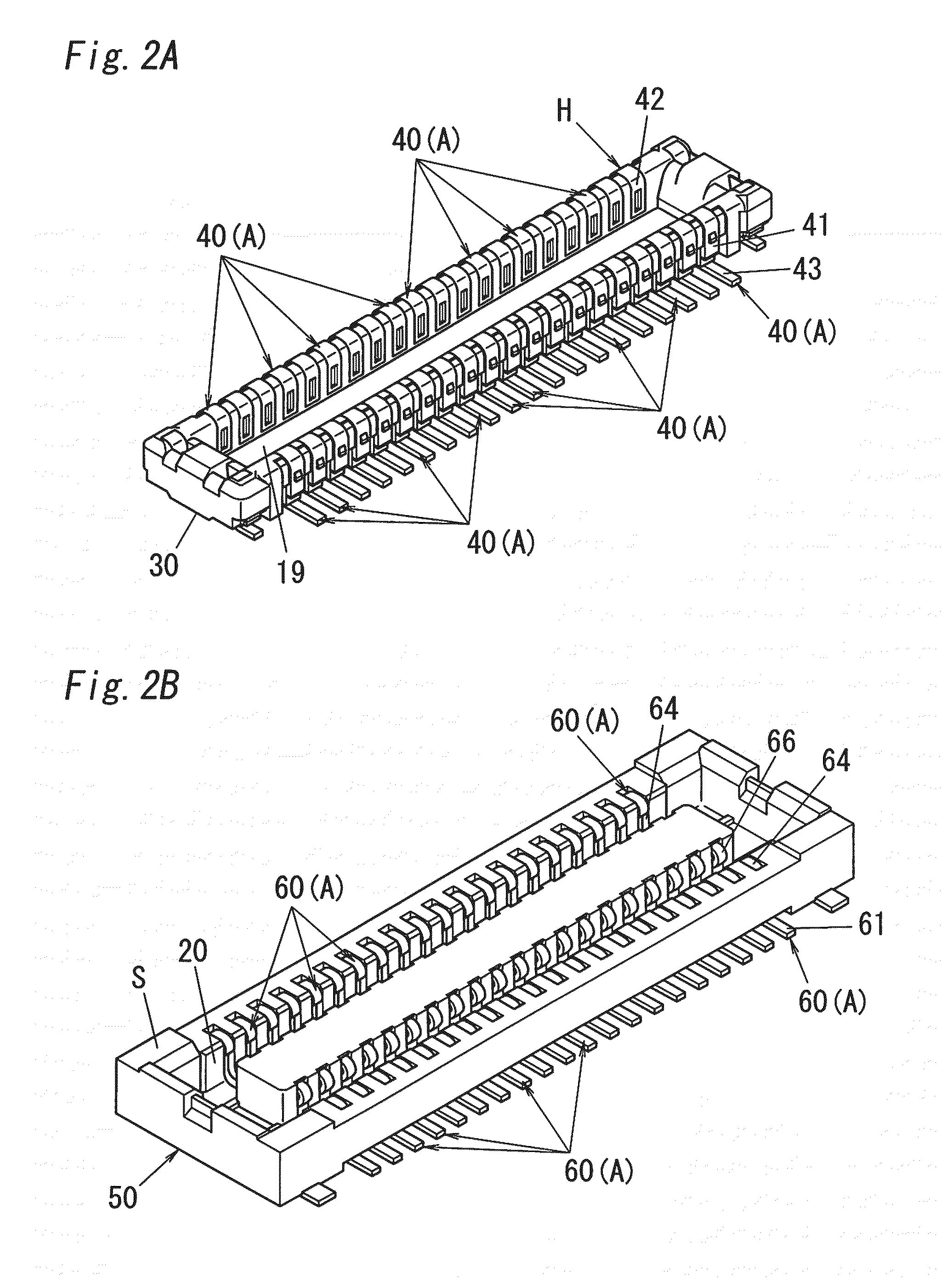
[0050]Examples of the connector using the electrical contact component A include a connector having a header H shown in FIG. 2A and a socket S shown in FIG. 2B. The header H includes a header body 30 and a plurality of header contacts 40. The header body 30 is made of an insulation material such as a synthetic resin. The header contacts 40 are made of an electrical conducting material. The header contacts 40 are held by the header body 30 according to insert molding, for example. The socket S includes a socket body 50 and a plurality of socket contacts 60. The socket body 50 is made of an insulation material such as a synthetic resin ...

example 1

[0080]A Cu alloy such as phosphor bronze or titanium copper was used as a material of a base material 3. The Cu alloy was molded into a shape applied to a copper plate or a contact point material of a switch.

[0081]A CNT plating layer 4 of a contact point part 1 was formed by an electrolysis plating method. In this case, a Ni plating liquid containing CNTs 4b was used. VGCF manufactured by Showa Denko K.K. was used as the CNT 4b. The CNTs 4b were used a mixture of single wall CNTs and multi wall CNTs. The Ni plating liquid contained the CNTs 4b, each of which has a diameter (outer diameter) of 100 to 200 nm and a length of 10 to 20 μm. The Ni plating liquid contained nickel sulfate (1 mol / dm3), nickel dichloride (0.2 mol / dm3), boron (0.5 mol / dm3), and a polycarboxylic acid (2×10⁻⁵ mol / dm3) having a molecular weight of 5000 as a dispersant. The mixed amount of the CNTs 4b was set to 2 g / dm3. The nickel plating liquid containing the CNTs 4b was used as a plating bath. Plating was carri...

example 2

[0083]Example 2 was carried out in the same manner as in example 1 except that a CNT plating layer 4 was formed, which had a metal plating film 4a having a thickness of 20 μm.


PUM

PropertyMeasurementUnit
thicknessaaaaaaaaaa
thicknessaaaaaaaaaa
lengthaaaaaaaaaa

Abstract

An electrical contact component includes a contact point part configured to provide an electrical connection by contact, and a mounting part configured to provide an external electrical connection by solder joining. A plating layer containing carbon nanotubes or carbon blacks is selectively formed on the surface of the contact point part. A plating layer having higher solder wettability than that of the plating layer containing the carbon nanotubes or carbon blacks is formed on the mounting part.

Description

TECHNICAL FIELD[0001]The present invention relates to an electrical contact component used as a contact point component (contact point material) for an electric component such as a relay (for example, a power relay of an electronic vehicle), a switch, a connector, or a breaker.BACKGROUND ART[0002]Heretofore, there has been provided an electronic component described in, for example, Japan Patent Publication No. 4032116. The electronic component has a wiring pattern.[0003]In the electrical contact component, an expensive noble metal layer made of Au, Ag, Pt, Rh, Ru, Ir, or Pd or the like having excellent electrical conductivity is generally formed on the outermost surface of a contact point part in order to secure contact reliability and mountability. Since Au or Ag is a soft material, Au or Ag is often used as an alloy or a composite material such as Au—Co, Au—Ni, Ag—W, Ag—WC, Ag—Cu, Ag—Mo, Ag—CdO, Ag—Au, Ag—SnO, Ag—Pd, Ag—Ni, or Ag—ZnO in order to increase the hardness thereof. Au o...

Claims


Application Information

Patent Timeline
Patent Type & Authority Applications(United States)
IPC IPC(8): H01R13/02
CPCH01R13/02C23C18/1603C23C18/1651C23C18/1662C25D3/12C25D3/62C25D5/02C25D5/026C25D5/12C25D15/00C25D5/605C25D5/619H01R12/716H01R13/03
Inventor SEKI, NAOKIYAMADA, KATSUNOBUUCHIDA, YUICHIARAI, SUSUMU
Owner PANASONIC CORP
Learn More