
Systems and methods for thermophotonic dynamic imaging

a dynamic imaging and thermophotonic technology, applied in the field of systems and methods of thermophotonic dynamic imaging, can solve the problems of significant limitations on depth and/or spatial resolution, unable to meet the specific application requirements of some specific applications, and often fail in applications that require higher sensitivity, etc., and achieve the effect of high signal-to-noise ratio

Active Publication Date: 2014-03-27
MANDELIS ANDREAS +2
View PDF12 Cites 24 Cited by
  • Summary
  • Abstract
  • Description
  • Claims
  • Application Information

AI Technical Summary

Benefits of technology

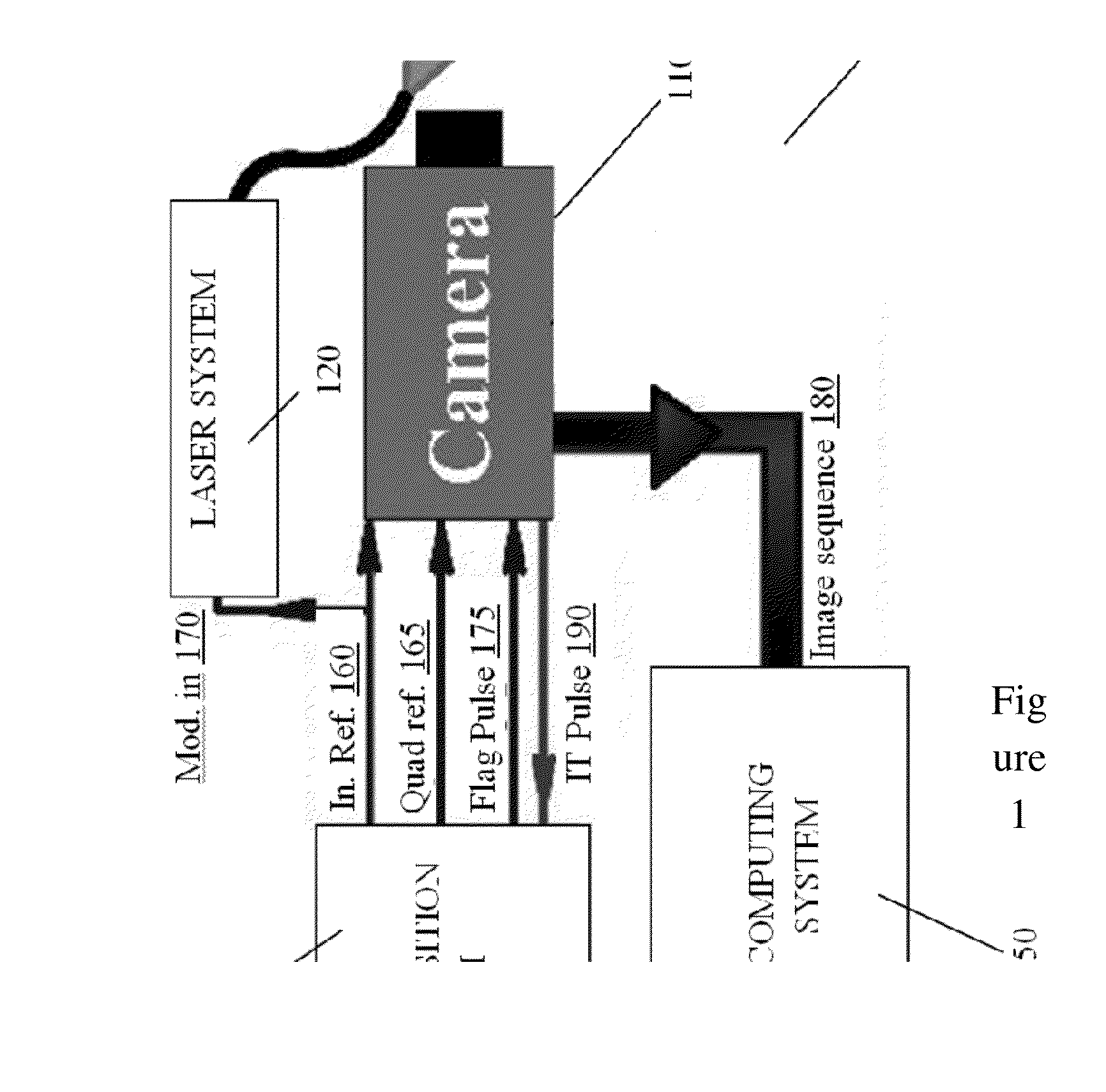
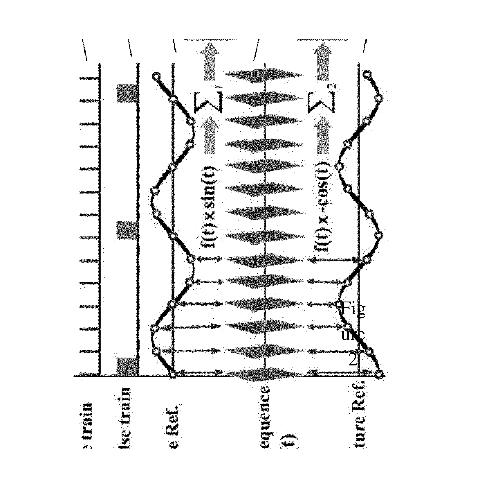
This patent describes a system and method for improved thermophotonic imaging that can obtain both amplitude and phase information with high signal-to-noise ratios and depth-resolved capabilities. The system uses a modulated optical beam to illuminate a sample and an imaging camera to capture the photothermal radiation. The recorded image frames are then processed to extract the amplitude and phase information. The system can be used in a variety of applications, such as non-destructive testing and biomedical diagnostic imaging. The technical effects of this patent include improved accuracy and resolution of thermophotonic imaging, as well as the ability to measure changes in the sample over time.

Problems solved by technology

Such methods, while well suited for some specific applications, often fail in applications that demand higher sensitivity.
Another disadvantage of known thermographic and thermophotonic imaging methods is the use of low speed imaging techniques, which can place significant limitations on depth and / or spatial resolution.

Method used


Image

  • Systems and methods for thermophotonic dynamic imaging
  • Systems and methods for thermophotonic dynamic imaging
  • Systems and methods for thermophotonic dynamic imaging

Examples


example 1

Early Detection of Dental Caries

[0119]In order to apply controlled demineralization to tooth samples, a demineralizing / artificial caries solution was prepared. The solution was an acidified gel, consisting of 0.1 M lactic acid gelled to a thick consistency with 6% w / v hydroxyethylcellulose and the pH adjusted to 4.5 with 0.1 M NaOH. Demineralization with acidified gel approximates the natural carious lesion as it mimics the properties of actual dental plaques in the oral cavity. Previous studies show that this solution can produce a subsurface lesion in enamel with a sound surface layer which is characteristic of an early carious lesion1.

[0120]As it was desired to observe the contrast between demineralized and healthy areas in a whole tooth, a treatment protocol was followed in which the interrogated surface of the sample was covered with two coatings of commercial transparent nail polish except for a rectangular or square window, henceforth referred to as the treatment window. The ...

example 2a

Non-Destructive Testing of Engineering Materials With Subsurface Absorbers and Early Detection of Dental Caries Using Thermophotonic Radar Imaging

[0130]The physical principles of light absorption / scattering and thermal-wave generation are the same for the various imaging modalities disclosed herein. The difference lies in the applied optical excitation pattern and the subsequent signal processing algorithm. As discussed above, in thermal wave radar (or thermophotonic radar) imaging a chirp excitation is used instead of a single frequency modulation. As a result, according to equation 5a, the thermal diffusion length is not fixed and the generated thermal-waves dynamically scan a series of depths. One of the problems encountered in thermophotonic lock-in imaging is the compromise one needs to make between the maximum detection depth and the depth resolution. While the low frequency thermal-waves can see deep into the sample, they lack the desired depth resolution; the high frequency ...

example 2b

Non-Destructive Testing of Engineering Materials With Subsurface Absorbers and Early Detection of Dental Caries Using Binary Phase Code Imaging

[0138]Table 1 (shown above) includes the binary phase codes up to 16 bits. These codes are used as an envelope of a single-frequency modulated signal to yield the reference signal for binary phase code imaging.

[0139]Samples B1 and B3 (FIG. 7(a) and (c)) were used to study the capabilities of binary phase code imaging. FIG. 11 shows the results obtained from sample B1 using a 7-bit binary phase coding on a 1 Hz carrier signal (FIGS. 11(a) and (c)) as well as those of thermophotonic lock-in imaging at 1 Hz (FIGS. 11(b) and (d)). It can be seen that due to the advantages of matched filtering / cross-correlation the binary phase code image resolves all the steps while the thermophotonic lock-in image can statistically detect only the first two steps. That is, binary phase code imaging has a significantly better depth resolution compared to thermoph...


PUM


Abstract

Systems and methods for improved thermophotonic imaging are provided in which both amplitude and phase image information is obtained with a high signal to noise ratio and depth-resolved capabilities. Image data obtained from an imaging camera is dynamically averaged and subsequently processed to extract amplitude and / or phase image data. The system may be configured for a wide range of imaging modalities, including single frequency modulation (thermophotonic lock-in imaging), Thermal-Wave Radar imaging or Thermophotonic Radar imaging involving chirp modulation, and Binary Phase Coded Modulation. Such imaging modalities may find application in many diverse areas, including non-destructive testing and biomedical diagnostic imaging including the imaging of teeth and monitoring changes in the tooth over time which are due to pathology such as dental caries or erosion.

Description

CROSS-REFERENCE TO RELATED APPLICATION[0001]This application claims priority to U.S. Provisional Application No. 61 / 471,772, titled “SYSTEMS AND METHODS FOR THERMOPHOTONIC DYNAMIC IMAGING” and filed on Apr. 5, 2011, the entire contents of which are incorporated herein by reference.BACKGROUND OF THE INVENTION[0002]This invention relates to systems and methods of non-destructive subsurface imaging. More particularly, this invention relates to systems and methods for thermophotonic imaging.[0003]Thermographic and thermophotonic imaging methods have found widespread use in applications such as non-destructive testing of various materials and biomedical diagnostic imaging. While numerous methods have been developed and described in the literature, most solutions proposed to date have relied on methods involving single frequency analysis of amplitude and phase images. Such methods, while well suited for some specific applications, often fail in applications that demand higher sensitivity....

Claims


Application Information

Patent Timeline
Patent Type & Authority Applications(United States)
IPC IPC(8): H04N7/18
CPCH04N7/183A61B5/0073A61B5/0088G01N21/71
Inventor MANDELIS, ANDREASTABATABAEI, NIMAABRAMS, STEPHEN
Owner MANDELIS ANDREAS
Learn More