Heat transfer pipe for heat exchanger

a technology of heat exchanger and heat transfer pipe, which is applied in the direction of heat transfer modification, lighting and heating apparatus, tubular elements, etc., can solve the problems of increasing the roughness of the heat transfer pipe, increasing the manufacturing cost, etc., and achieves the effect of less resistance to fluids and improving the operating efficiency of the whole heat exchanger

Inactive Publication Date: 2014-03-27
LUVATA ALLTOP ZHONGSHAN LTD
View PDF9 Cites 5 Cited by
  • Summary
  • Abstract
  • Description
  • Claims
  • Application Information

AI Technical Summary

Benefits of technology

The invention provides a heat transfer pipe for heat exchanger that improves heat transfer efficiency without increasing resistance to a fluid, and has a simple structure and low manufacturing cost. The heat transfer pipe has protrusions that enhance fluid turbulence and form more cores for bubbles during evaporation, improving heat exchange efficiency. The protrusions are smaller in width than the grooves where they are located, reducing fluid resistance. The section of each protrusion is a trapezoid, which further enhances turbulence and improves heat exchange. The protrusions are formed with gradually decreased radial height, which reduces resistance to fluid and avoids too great pressure decrease. This improves the operating efficiency of the whole heat exchanger.

Problems solved by technology

On the basis of this, some heat transfer pipes are provided with, in addition to the primary teeth, intermittent secondary teeth with lower heights and disposed between the primary teeth, which results in further increasing the roughness within the heat transfer pipes.
Moreover, the shaping and positioning of the secondary teeth is not optimized with regard to the kinetics of the fluid, it is thereupon inconvenient to manufacture, which, de facto, raises the cost of manufacturing.

Method used


Image

  • Heat transfer pipe for heat exchanger
  • Heat transfer pipe for heat exchanger
  • Heat transfer pipe for heat exchanger

Examples


Embodiment Construction

[0022]Hereinafter, particular embodiments of the heat transfer pipe for heat exchanger according to the invention are described in detail with references to the drawings.

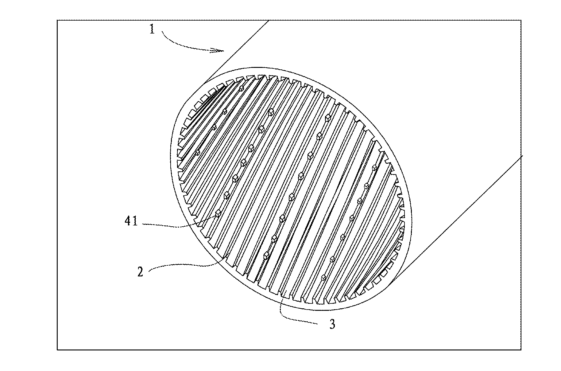
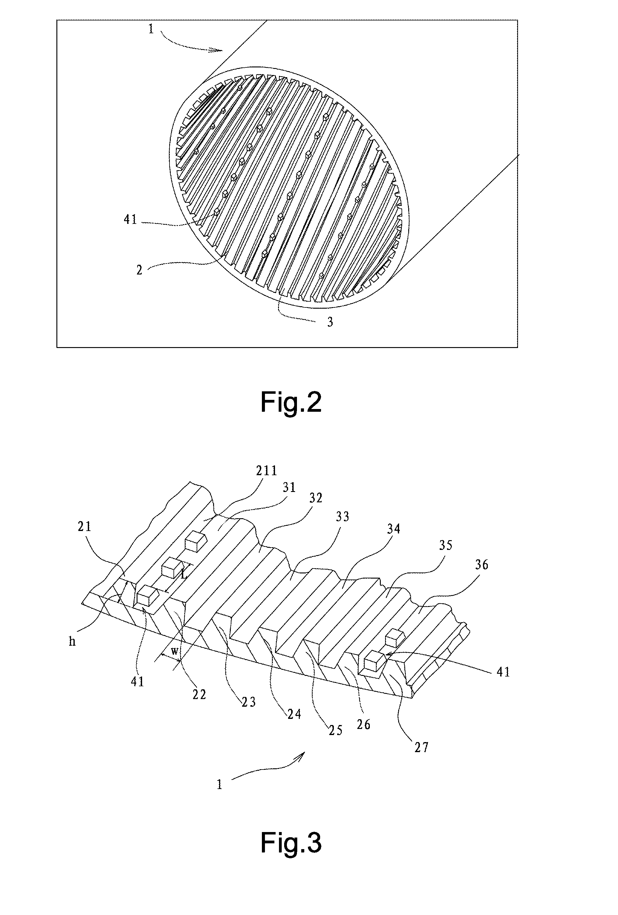
[0023]FIG. 2 shows a schematic perspective view of a part of a heat transfer pipe 1 according to the first embodiment of the invention. As shown in FIG. 2, the heat transfer pipe 1 is formed as a cylinder pipe, preferably of copper. Without doubt, the heat transfer pipe 1 can be made of other alloy materials. A plurality of helical primary teeth 2 are manufactured and formed in the inner surface of the heat transfer pipe 1 (particularly, shown as 21, . . . , 26, and 27 in FIG. 3). Accordingly, grooves 3 are formed between two adjacent primary teeth (particularly, shown as 31, 32, 33, 34, 35, and 36 in FIG. 3). Furthermore, protrusions 41 disposed intermittently and having heights lower than primary teeth are formed in some of the grooves 3. The protrusions further increase the roughness within the heat transfer pipe...


PUM


Abstract

The invention provides a heat transfer pipe for heat exchanger, an inner surface of the heat transfer pipe being provided alternately with a plurality of helical primary teeth (21, 22, 23, 24, 25, 26, 27) and a plurality of grooves (31, 32, 33, 34, 35, 36), each groove being disposed between adjacent primary teeth, wherein a protrusion set is provided in at least one groove (31, 36), the protrusion set comprises a plurality of protrusions (41) sequentially and intermittently disposed in an extending direction of the primary teeth, and each protrusion (41) has a radial height lower than those of the primary teeth, and wherein at least one groove having no protrusion set (32, 33, 34, 35) is provided between the adjacent ones (31, 36) of the grooves each having a protrusion set. In this way, the above heat transfer pipe suppresses significantly increasing flow resistance of a fluid, and is easy to manufacture with low manufacturing cost, at the same time of improving the efficiency of heat exchange.

Description

TECHNICAL FIELD[0001]This invention relates to a heat transfer pipe for heat exchanger, more particularly to a heat transfer pipe with helical rifling or helical primary teeth.BACKGROUND[0002]A heat exchanger is an apparatus that makes it possible to exchange energy between two or more fluids for the purpose of heating, cooling and etc. In a heat exchanger regularly used nowadays, fluids under heat exchange are separated from each other with a solid dividing wall or a third fluid. The design of the heat transfer pipe for the heat transfer has great influence on the operating efficiency of the heat exchanger.[0003]FIG. 1 shows a typical heat transfer apparatus 100, which comprises a plurality of fins 101 and a plurality of heat exchange pipes 102. Lines of holes are provided in the fins 101, and the heat exchange pipes are inserted into these holes. During operation, a first fluid enters into the heat transfer pipe system comprising the plurality of heat exchange pipes 102, as the ar...

Claims


Application Information

Patent Timeline
Patent Type & Authority Applications(United States)
IPC IPC(8): F28F1/40
CPCF28F1/40F28F13/187F15D1/02F28F1/00F28F1/02F28F13/18
Inventor DENG, WENJIA
Owner LUVATA ALLTOP ZHONGSHAN LTD
Why Eureka
Try Eureka