Distillation column and method for distilling acrylic acid

a technology of distillation column and distillation method, which is applied in the direction of filtration separation, organic chemistry, separation process, etc., to achieve the effect of less satisfactory separation results, high separation efficiency and good particle separation

Active Publication Date: 2014-03-06
LURGI
View PDF2 Cites 0 Cited by
  • Summary
  • Abstract
  • Description
  • Claims
  • Application Information

AI Technical Summary

Benefits of technology

[0010]In addition, this invention comprises the use of the distillation column according to the invention for the distillation of acrylic acid, in which raw acrylic acid, which still contains undesired amounts of acrylic acid oligomers, is obtained at the top of the column as pure acrylic acid free from oligomers. A particularly advantageous aspect of the distillation column for this use provides that a distillation column according to claim 1 is used, wherein the evaporator circulation (5′) is 20 to 200, preferably 40 to 120 m3 / (h*m2) and the size of the stream (12″) withdrawn from the bottom for further treatment is 0.1 to 5, preferably 0.2 to 3 m3 / (h*m2), each based on the inner cross-sectional area of the column, wherein the ratio of the diameter of the column (1″) and of the bottom (2″) is 1:0.1 to 0.9, preferably 1:0.15 to 0.6, and wherein the upwardly directed flow velocity in the sedimentation zone (3″) is 0.05 to 1, preferably 0.1 to 0.6 m / s. The objective of the invention to obtain a rather small amount of precipitated solid or gel particles in the evaporator circulation is achieved best when said parameters are maintained. This is true in particular when the distillation column according to the invention is used for the distillation of acrylic acid; in this separation operation in particular particles of acrylic acid polymer are obtained in the bottom of the column. When designing the distillation column within the parameter ranges taught in claim 1, a good particle separation is achieved and at the same time a high separation efficiency with regard to the pure acrylic acid. Other designs of the distillation column outside the features of claim 3 provide less satisfactory separation results with regard to the particle separation. Retracting the bottom of the column, i.e. designing the bottom of the column with a smaller diameter than the column, has proven quite effective in the distillation of acrylic acid, as this provides for a more accurate measurement of the amount of liquid present in the bottom.

Problems solved by technology

Other designs of the distillation column outside the features of claim 3 provide less satisfactory separation results with regard to the particle separation.

Method used


Image

  • Distillation column and method for distilling acrylic acid
  • Distillation column and method for distilling acrylic acid
  • Distillation column and method for distilling acrylic acid

Examples


Embodiment Construction

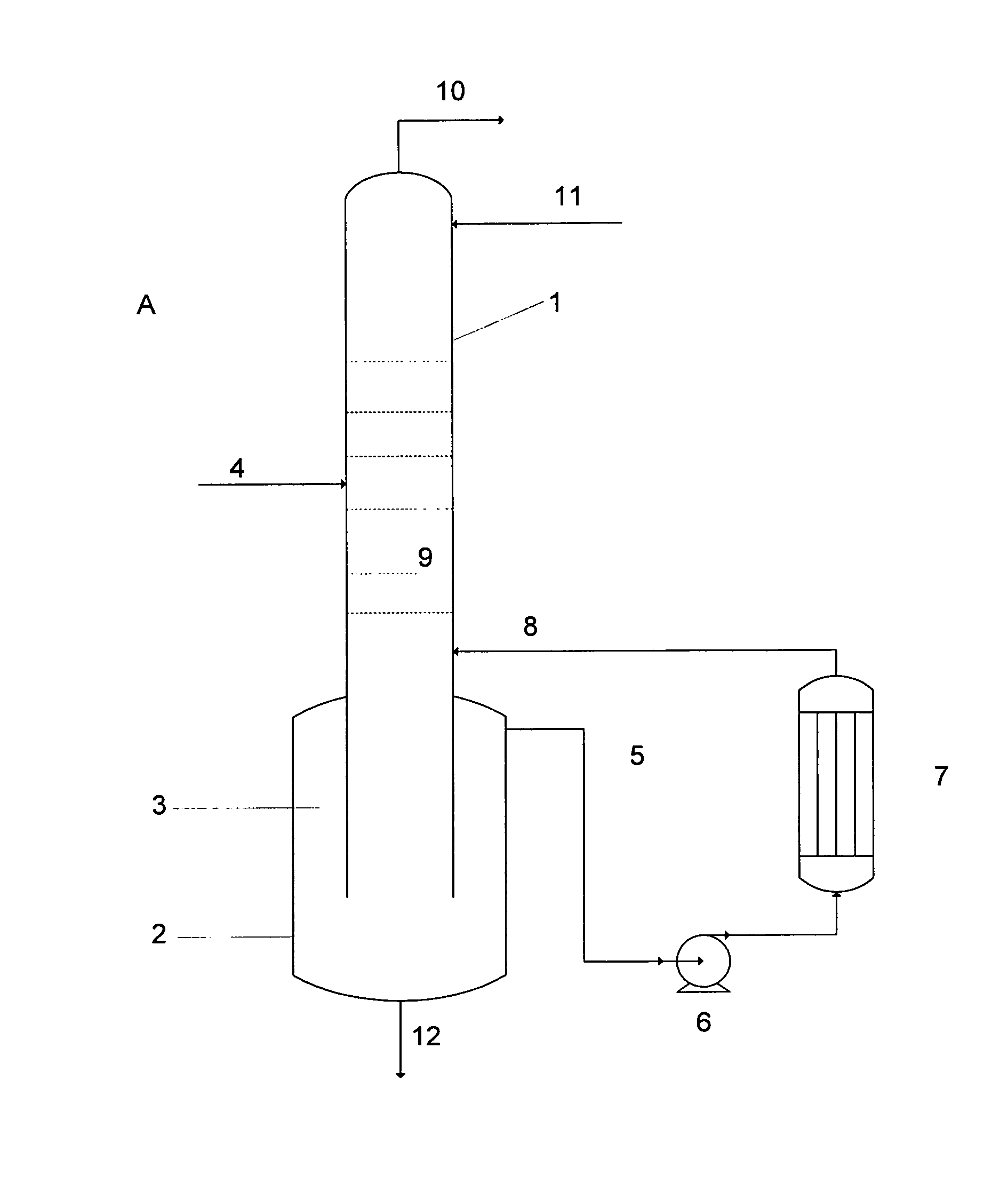
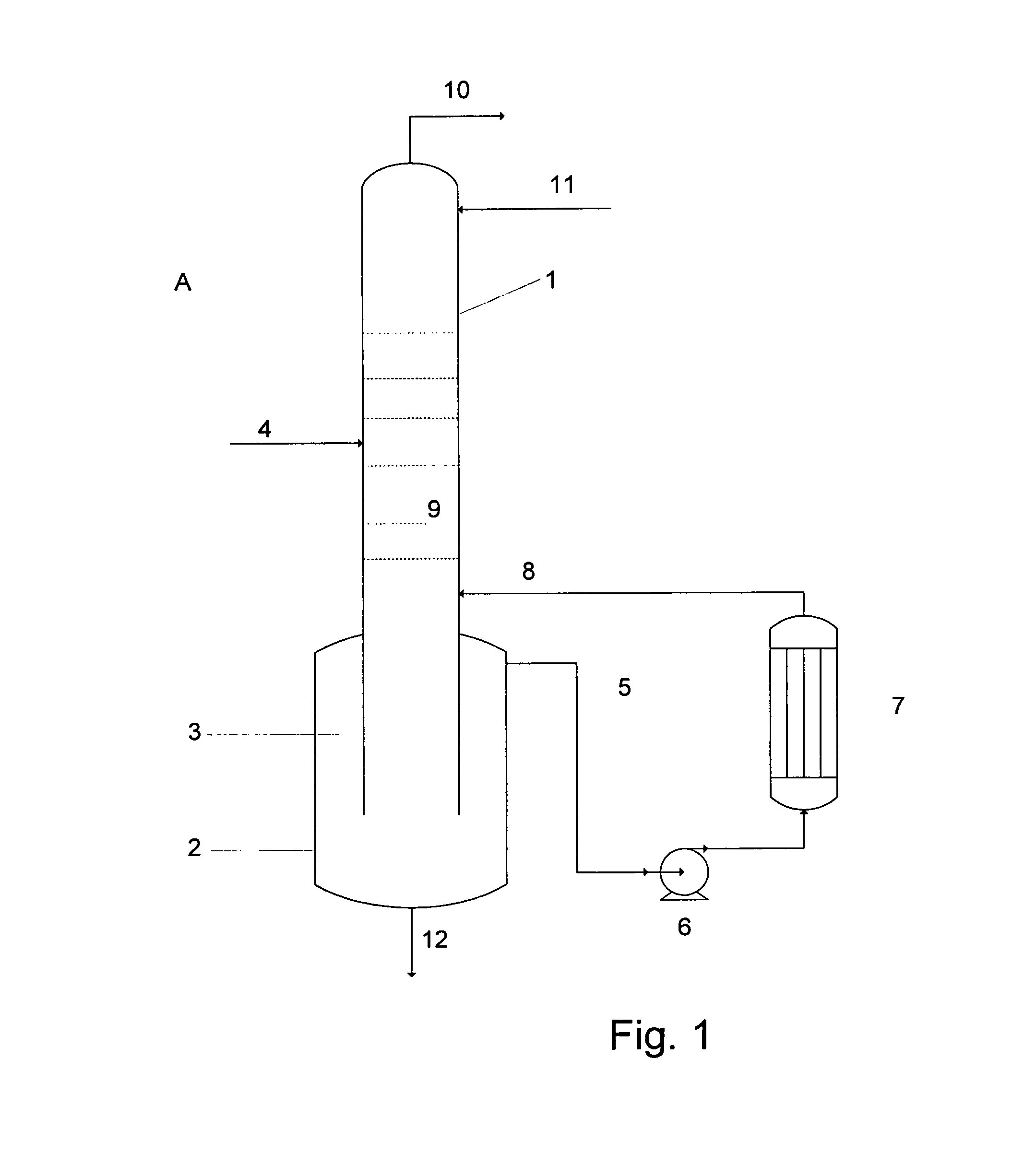
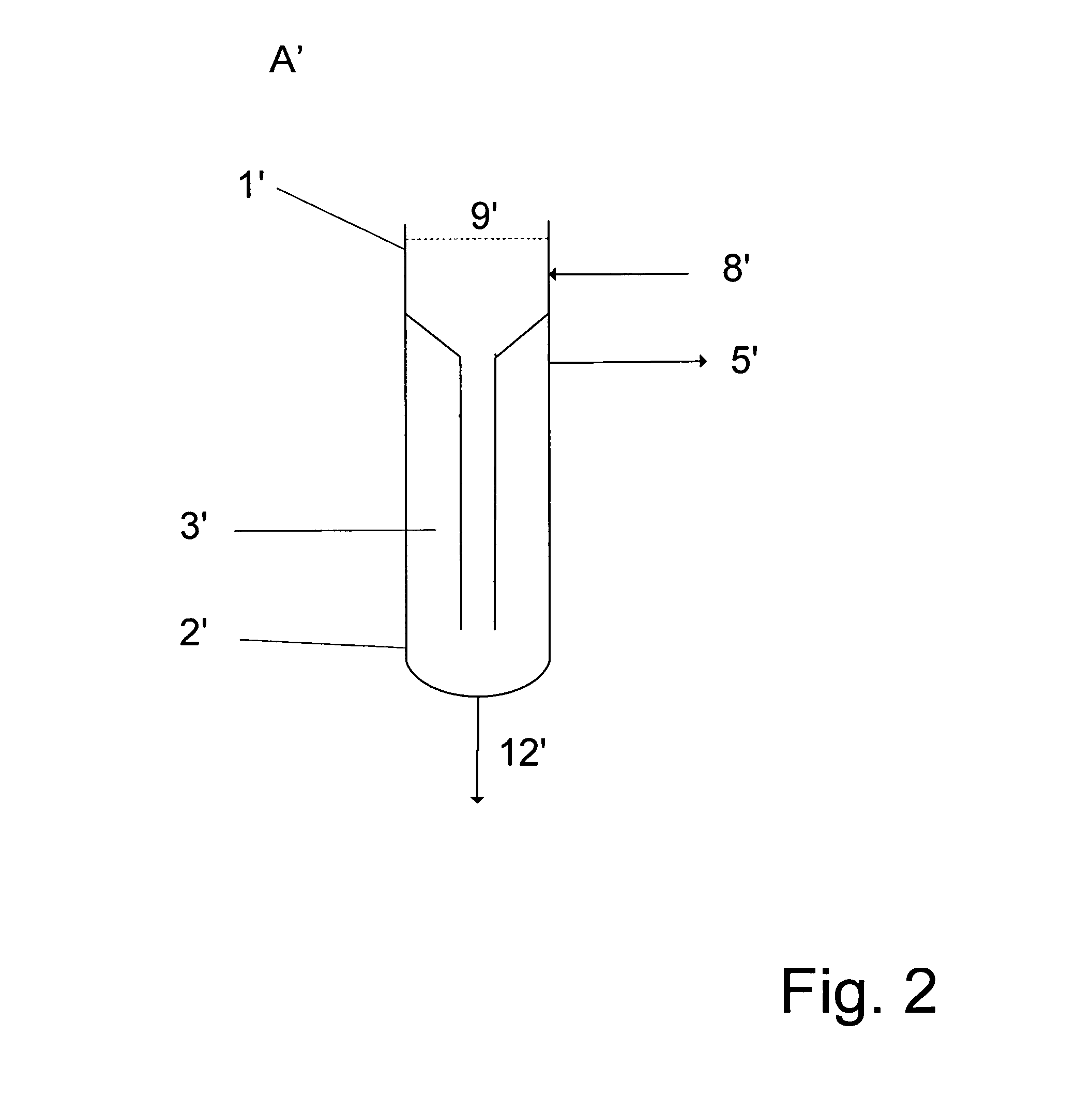
[0016]The distillation column (A, A′, A″) substantially consists of the column (1, 1′, 1″) and the column bottom (2, 2′, 2″). The column bottom is equipped with the sedimentation zone (3, 3′, 3″). The design of the sedimentation zone depends on the parameters of the respective process for which the column is used. The size of the mass flows, the material properties of the substances present and the space conditions present at the site of erection of the column will have to be considered.

[0017]FIG. 1 shows a sedimentation zone protruding beyond the cross-section of the column. This construction is to be preferred when the sedimentation of the particles in the bottom product only takes place slowly and therefore a great retention time is required in the sedimentation zone.

[0018]FIG. 2 shows an embodiment in which the sedimentation zone is placed in the cross-section of the column. This construction is to be preferred when the space conditions are confined and such great retention time...


PUM

PropertyMeasurementUnit
velocityaaaaaaaaaa
densityaaaaaaaaaa
diameteraaaaaaaaaa

Abstract

A distillation column with external circulation evaporator and a sedimentation zone in the bottom of the column, from which the evaporator circulation is fed, and use of the distillation column according to the invention for the distillation of acrylic acid.

Description

BACKGROUND OF THE INVENTION[0001]This is a 371 of PCT / EP2011 / 006199 filed 9 Dec. 2011 (international filing date), and claiming priority of German Application 10 2011 013 561.8, filed Mar. 10, 2011FIELD OF THE INVENTION[0002]This invention relates to a distillation column with external circulation evaporator, which is in particular suitable for carrying out distillation processes in which solid or gel-like constituents are present in the bottom of the column. This invention also relates to a process for the distillation of acrylic acid by using a distillation column according to the invention.[0003]The term distillation column subsequently will be used as generic term which also includes the term rectification column as well as single-stage processes for separation by evaporation, such as the so-called flash distillation.[0004]Distillation columns with external circulation evaporator are known; they are described in principle e.g. in the book: Technische Chemie, 2006 Wiley-VCH Verla...

Claims


Application Information

Patent Timeline
Patent Type & Authority Applications(United States)
IPC IPC(8): B01D3/32
CPCB01D3/32B01D3/322C07C51/44C07C57/04
Inventor BAUER, JOCHENCASTILLO-WELTER, FRANKKREICH, MARKUSKIRSTEN, KLAUSSTEDEN, CHRISTOPHWALTER, DOMINIC
Owner LURGI
Why Eureka
Try Eureka