
Light-conducting component for constructions and buildings and also production process therefor

a technology of construction and building, which is applied in the field of light-conducting components, can solve the problems of relatively labor-intensive production of the entire multi-layer composite construction element, and achieve the effect of reducing the cost of production

Inactive Publication Date: 2014-03-06
CHRISTANDL DIETER +2
View PDF26 Cites 16 Cited by
  • Summary
  • Abstract
  • Description
  • Claims
  • Application Information

AI Technical Summary

Benefits of technology

The present invention provides a way to modify components, like masonry bricks, by using a matrix made of a polymer foam, which is faster and cheaper to produce than prior art methods. The foam is reinforced with a light-conducting pegs that are formed in an injection molding process. The resulting component is lightweight, easy to produce, and can be used for suspended ceilings. The lattice elements in the foam support the component during casting, and the position of the elements remains stable. Overall, the invention allows for rapid and cost-effective modification of components.

Problems solved by technology

The light-conducting components of the aforementioned prior art are characterized in that they have several glass fibers or glass fiber bundles that are cast into concrete, which typically do not remain at their prescribed location during casting of the concrete and are possibly damaged.
In this prior art publication, several layers with recesses for the rigid light-conducting elements are required so that the entire multilayer composite construction element is relatively labor- and cost-intensive in production.

Method used


Image

  • Light-conducting component for constructions and buildings and also production process therefor
  • Light-conducting component for constructions and buildings and also production process therefor
  • Light-conducting component for constructions and buildings and also production process therefor

Examples


first embodiment

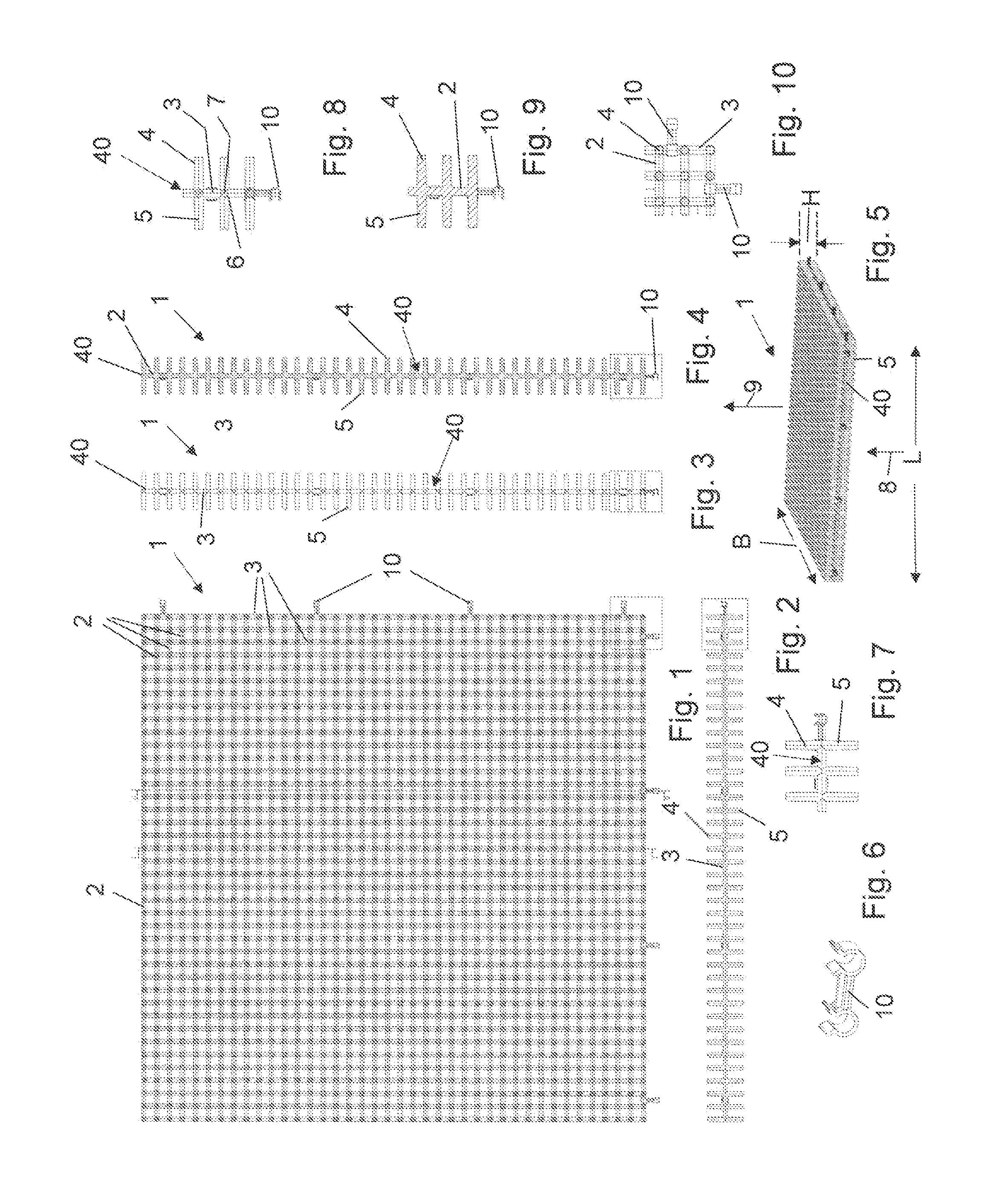
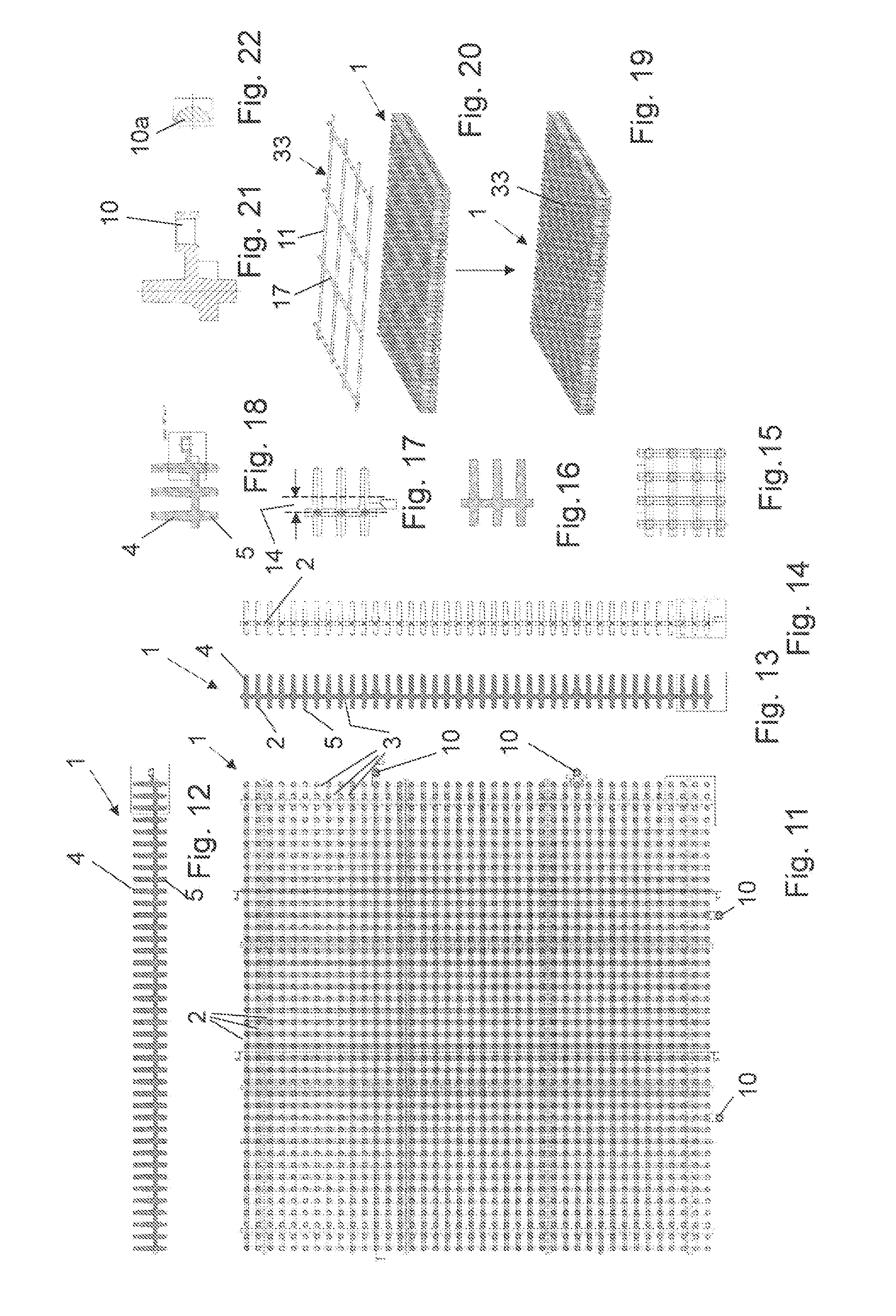
[0006]In a first embodiment the light-conducting pegs are produced in one piece in an injection molding die together with a light-conducting element formed as a lattice mat. This means that the injection molding mass in an injection molding die consists of a light conducting plastic and a flat support mat, consisting of intersecting and bonded longitudinal and transverse rods, is present in a (preferably) single injection molding process, at whose intersection points the light-conducting pegs protruding in a vertical direction from it are molded-on. Particularly simple production of an integral part is thus obtained, since this part in a subsequent work step is inserted into a casting mold and provided in alternation initially with a one-sided or two-sided insulation and / or reinforcement and then cast with a curable filling compound so that only the light-absorbing and light-emitting faces of the light-conducting pegs are still recognizable on the opposite flat sides of the board so...

second embodiment

[0008]In a second embodiment the lattice mat also consists of longitudinal and transverse rods intersecting in a plane, but in which the light-conducting pegs are not molded onto the intersection points of the longitudinal and transverse rods but into the openings between the longitudinal and transverse rods.

third embodiment

[0009]In a third embodiment a two-stage injection molding process occurs, in which a lattice element or support mat is initially produced in a first step and the light-conducting pegs in a second step are molded onto selected points ((either at the intersection points of a lattice mat or the openings of a support mat (preferably not formed as a lattice) or lattice mat forming a framework)).

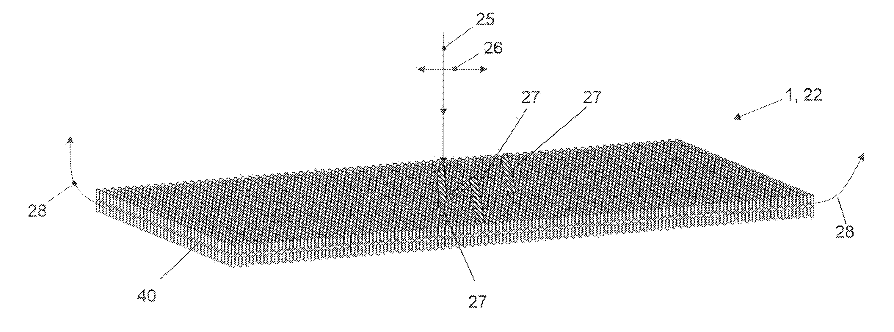
[0010]Aspects of the concept here are that the light-conducting element is formed from a light-conducting construction material (for example, PMMA plastic or glass) as self-supporting 2D or 3D lattice element from rods with a thickness / diameter greater than or equal to 1 mm, the self-supporting 2D or 3D lattice element having roughly the same or only slightly smaller width W or length L or base dimension W x L or total outside dimension W×L×H than the casting mold itself in which the light-conducting component was produced.

[0011]A molded element with light-conducting pegs embedded in it is disclos...


PUM

PropertyMeasurementUnit
Flexibilityaaaaaaaaaa
Shapeaaaaaaaaaa
Electrical conductoraaaaaaaaaa

Abstract

A light-conducting component, in particular finished concrete part in the form of a masonry brick, for constructions and building. The component is produced in a casting mold by casting into at least one casting building material and the optical waveguide is made of a light-conducting building material, e.g. PMMA polymer or glass, which is accessible at at least two positions on the outer surface of the light-conducting component for the input of light and output of light. The optical waveguide is configured as a self-supporting 2D or 3D lattice body composed of rods having a thickness / diameter of greater than 1 mm. The self-supporting 2D or 3D lattice body has approximately the same or an only slightly smaller width (W), or length (L), or base dimensions (W, L), or total external dimensions (W, L, H) than the casting mold itself.

Description

FIELD OF INVENTION[0001]The described embodiments of the present invention pertain to a light-conducting component, especially a finished concrete part in the form of a masonry brick, for structures and buildings, as well as its production method.BACKGROUND OF THE INVENTION[0002]Light-conducting building components are known in numerous forms from the prior art, for example, from German Utility Model DE 9310500 U1, PCT publication WO 03 / 097954 A1, and EPO publication EP 1305159 A1. The light-conducting components of the aforementioned prior art are characterized in that they have several glass fibers or glass fiber bundles that are cast into concrete, which typically do not remain at their prescribed location during casting of the concrete and are possibly damaged.[0003]German patent application DE 102007013199 A1 therefore proposes a multilayer composite construction element, whose several layers of concrete and insulation material are penetrated by a rigid light-conducting element...

Claims


Application Information

Patent Timeline
IPC IPC(8): E04C2/54F21V8/00B28B23/00E04C1/42
CPCE04C2/54B28B23/0037G02B6/0001E04C1/42Y10T428/24182
Inventor CHRISTANDL, DIETERCHRISTANDL, JOSEFHOFER, ROBERTFISHCER, OLIVER
Owner CHRISTANDL DIETER
Learn More