Silica container for pulling single crystal silicon and method for producing the same

Inactive Publication Date: 2014-02-13
SHIN ETABU QUARTZ PRODS
View PDF3 Cites 10 Cited by
  • Summary
  • Abstract
  • Description
  • Claims
  • Application Information

AI Technical Summary

Benefits of technology

The present invention is about a silica container for pulling single crystal silicon. The container has a smooth inner surface, which prevents the generation and growth of gaseous bubbles and reduces cavity defects in the resulting silicon wafer. The method for producing the container is low-cost. The main technical effect is to improve the quality of the pulled silicon ingot.

Problems solved by technology

However, since ultrapure quartz raw material powder is used in these production methods, these production methods are high in cost.
Moreover, problems related to the quality of single crystal silicon has arisen, such as silicon monoxide (SiO) gas that is generated as a result of the reaction between molten silicon and a silica crucible when the produced silica crucible is used and is then taken into single crystal silicon as gaseous bubbles (gas bubbles).
However, in addition to the high cost of the three-layer structure, the problem of gaseous bubbles formed of SiO or the like, the gaseous bubbles contained in the produced single crystal silicon, is not solved.
However, it is impossible to eliminate dissolved gas in the silica crucible wall completely only by sucking in the air present in a temporary compact of the silica powder under a reduced pressure.
Moreover, there is a problem of SiO gas that is generated by the reaction between molten silicon and a silica crucible when the silica crucible is used and is taken into single crystal silicon as gaseous bubbles.
However, the object of this invention is to pull single crystal silicon more stably by suppressing the vibration of the surface of silicon melt when the crucible is used, and therefore this does not prevent the generation of cavity defects such as gaseous bubbles in single crystal silicon to be pulled upwardly.
However, with such an irregular surface, degassing of the generated SiO gas to the outside of a silica container is inadequate, and, in particular, when single crystal silicon has a large diameter of 12 inches (300 mm) or more, it is difficult to achieve a sufficient reduction of cavities (voids) and non-through small-diameter holes (pinholes) in a silicon wafer made by slicing and polishing such single crystal silicon.
However, inadequate suppression of the reaction between a quartz crucible and silicon melt is achieved by merely adjusting the light transmittance.
However, since the Al concentration is in the high concentration range of 30 to 150 ppm, there arises a problem of an Al element taken into the produced single crystal silicon.
However, the viscosity of the quartz glass layer with the OH group concentration of 100 ppm or less is high at a high temperature and makes it harder for depressions to be formed in the inner surface, but, once depressions are formed, it becomes difficult to remove them.
However, since natural quartz glass contains various impurity metal elements in high concentrations, there arise a problem of contamination of ultrapure silicon melt.

Method used


Image

  • Silica container for pulling single crystal silicon and method for producing the same
  • Silica container for pulling single crystal silicon and method for producing the same
  • Silica container for pulling single crystal silicon and method for producing the same

Examples


example 1

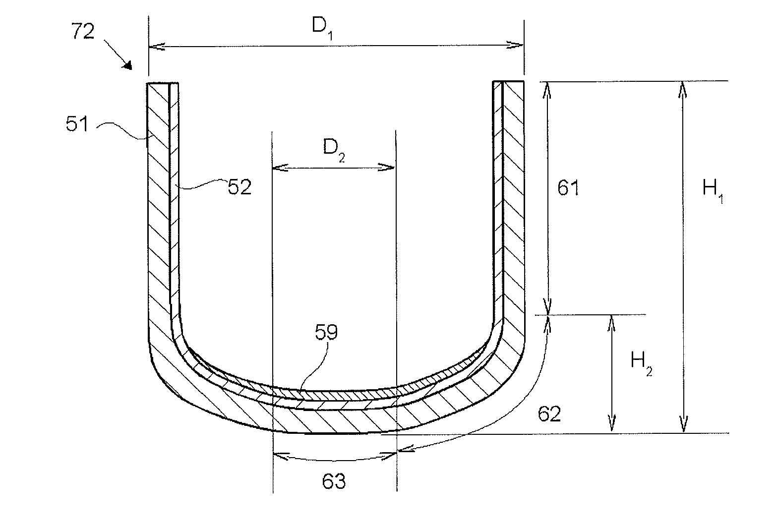
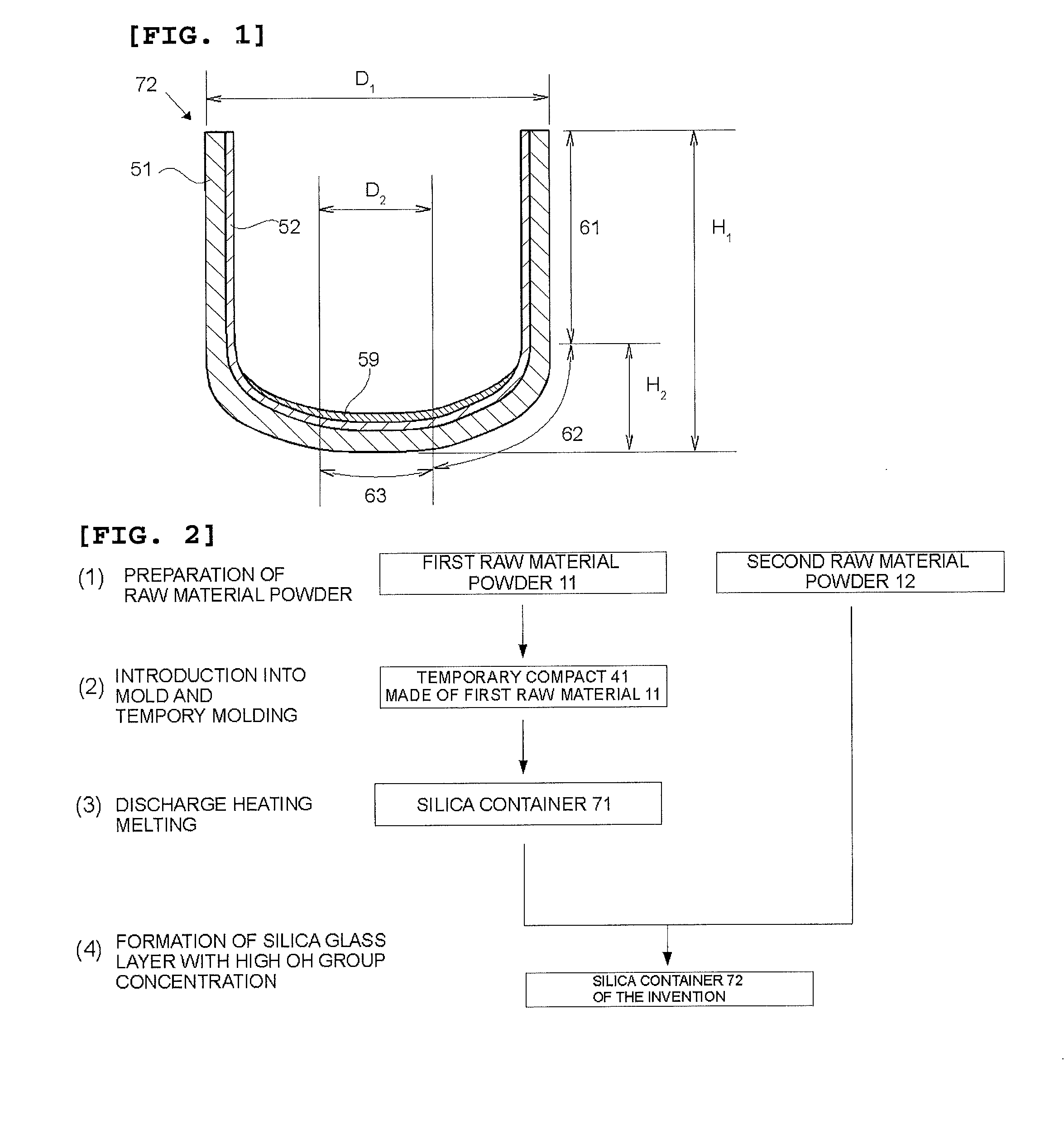
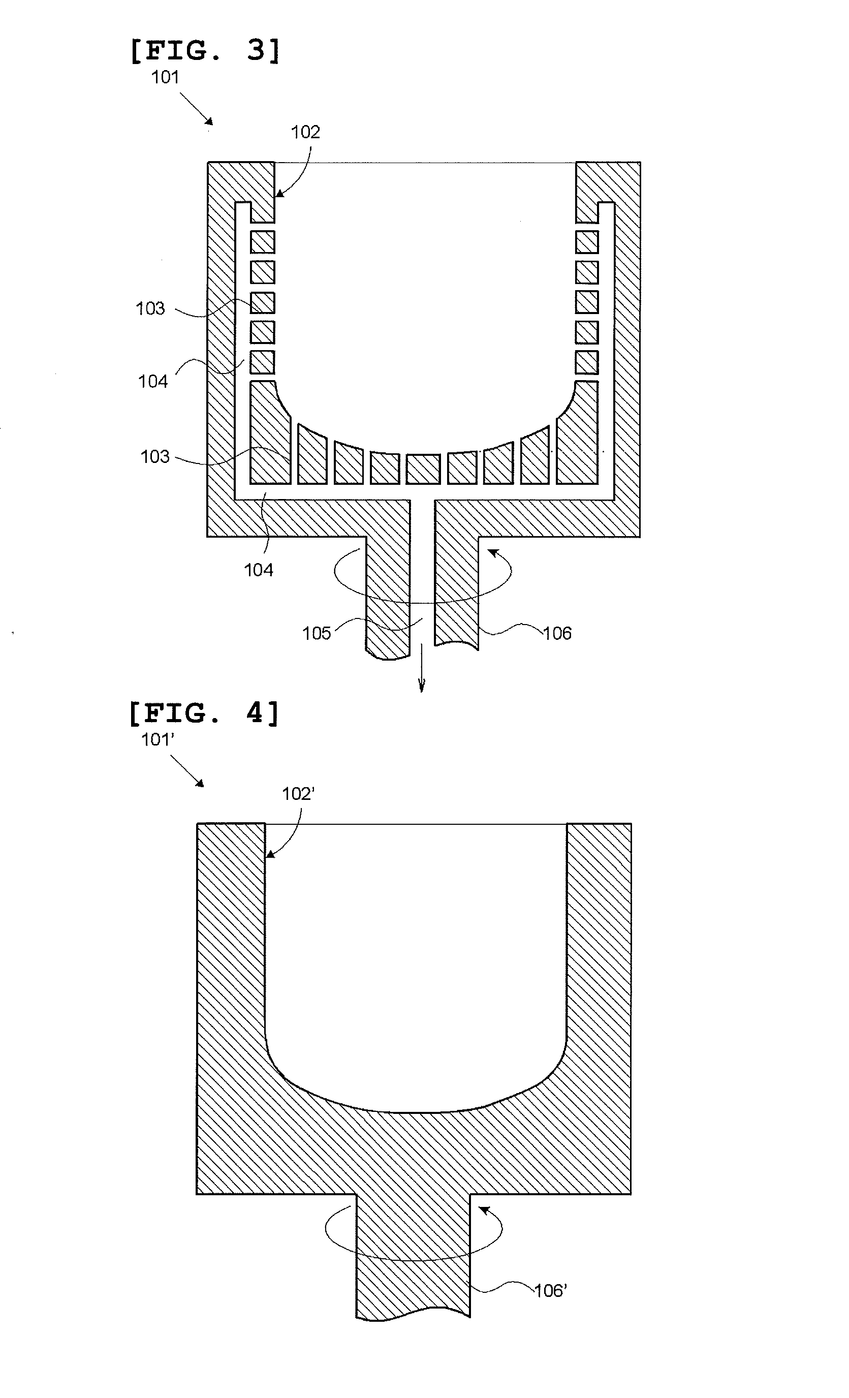
[0096]A silica container for pulling single crystal silicon was produced in accordance with the steps (1) to (4) described in FIG. 2. As the first raw material powder 11, a natural quartz powder having a particle size of 50 to 500 μm and purity of 99.999% by mass was prepared. The first raw material powder 11 was charged into the graphite mold 101 depicted in FIGS. 3 and 5 concurrently with the rotation of the graphite mold 101, whereby the temporary compact 41 made of the first raw material powder was obtained. Then, by using the apparatus depicted in FIGS. 6 and 7, discharge heating melting was performed in the temporary compact 41 made of the first raw material powder concurrently with suction under a reduced pressure from the periphery by using dried mixed gas of 95% by volume of N2 and 5% by volume of H2 as an inner atmosphere of the temporary compact 41 made of the first raw material powder. In this way, the silica container 71 whose outside was a white opaque silica sintered ...

example 2

[0097]By using the same second raw material powder 12 (second raw material powder a, a synthetic silica glass powder) as that of Example 1, a silica container was produced in basically the same manner as in Example 1, but the following changes were made. The first raw material powder 11 was obtained by mixing an aluminum nitrate solution to the first raw material powder 11 which was identical to that of Example 1 and drying it to add 10 ppm by mass of Al thereto. As an atmosphere at the time of discharge heating, dried mixed gas of 99% by volume of N2 and 1% by volume of H2 was used. The thickness of the silica glass layer 59 with a high OH group concentration, the silica glass layer 59 in a central portion of the container bottom portion, was set at 80 μm.

example 3

[0098]By using the same first raw material powder 11 as that of Example 1, a silica container was produced in basically the same manner as in Example 1, but the following changes were made. As the second raw material powder 12, high-purity synthetic silica glass powder (second raw material powder b) containing 550 ppm by mass of the OH group was used. The silica glass layer 59 with a high OH group concentration was made from the entire inner surface of the container bottom portion to the curved portion and was formed to have a thickness of 460 μm in a central portion of the container bottom portion.


PUM

PropertyMeasurementUnit
Lengthaaaaaaaaaa
Lengthaaaaaaaaaa
Fractionaaaaaaaaaa

Abstract

The present invention is directed to a silica container for pulling single crystal silicon, the silica container including a straight body portion, a curved portion, and a bottom portion, wherein the outside of the silica container is made of opaque silica glass containing gaseous bubbles, the inside of the silica container is made of transparent silica glass containing substantially no gaseous bubble, and, on the inner surface of the bottom portion, a silica glass layer containing the OH group in a concentration of more than 300 ppm by mass but 3000 ppm by mass or less, the silica glass layer having a thickness of 20 μm or more but 1000 μm or less, is formed. As a result, a low-cost silica container for pulling single crystal silicon, the silica container that can reduce cavity defects called voids and pinholes in pulled single crystal silicon, is provided.

Description

TECHNICAL FIELD[0001]The present invention relates to a silica container for pulling single crystal silicon and a method for producing the silica container.BACKGROUND ART[0002]In the past, as a method for producing a silica crucible for producing single crystal silicon for LSIs (large-scale integrated circuits), the production methods described in Patent Literature 1 and Patent Literature 2 have been used. These methods are the methods by which, after quartz powder or synthetic cristobalite powder which was processed to be ultrapure is charged into a rotating mold and is molded, electrodes are pushed thereinto from above and voltage is applied to the electrodes to produce arc discharge, whereby the temperature of an atmosphere is raised to a melting temperature range (which is estimated to be about 1800 to 2100° C.) of the quartz powder or the like to melt and sinter the quartz powder or the like. However, since ultrapure quartz raw material powder is used in these production method...

Claims


Application Information

Patent Timeline
IPC IPC(8): C30B15/10
CPCC30B15/10C03B19/095C03B2201/03C30B29/06C30B35/002Y10T117/1032Y02P40/57C03B20/00
Inventor YAMAGATA, SHIGERU
Owner SHIN ETABU QUARTZ PRODS
Why Eureka
Try Eureka