
Nanofiber membrane-electrode-assembly and method of fabricating same

a technology of nanofibers and electro-electrodes, which is applied in the field of fuel cells, can solve the problems of reducing the inherent mobility of hydrogen anions, affecting the ionic conduction of an aem, and exacerbate the problem of membrane brittleness

Active Publication Date: 2014-02-06
VANDERBILT UNIV
View PDF1 Cites 11 Cited by
  • Summary
  • Abstract
  • Description
  • Claims
  • Application Information

AI Technical Summary

Benefits of technology

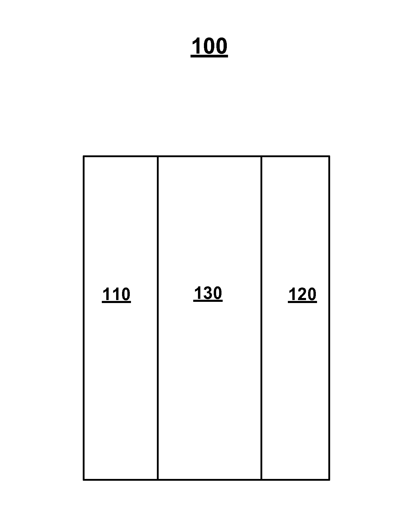
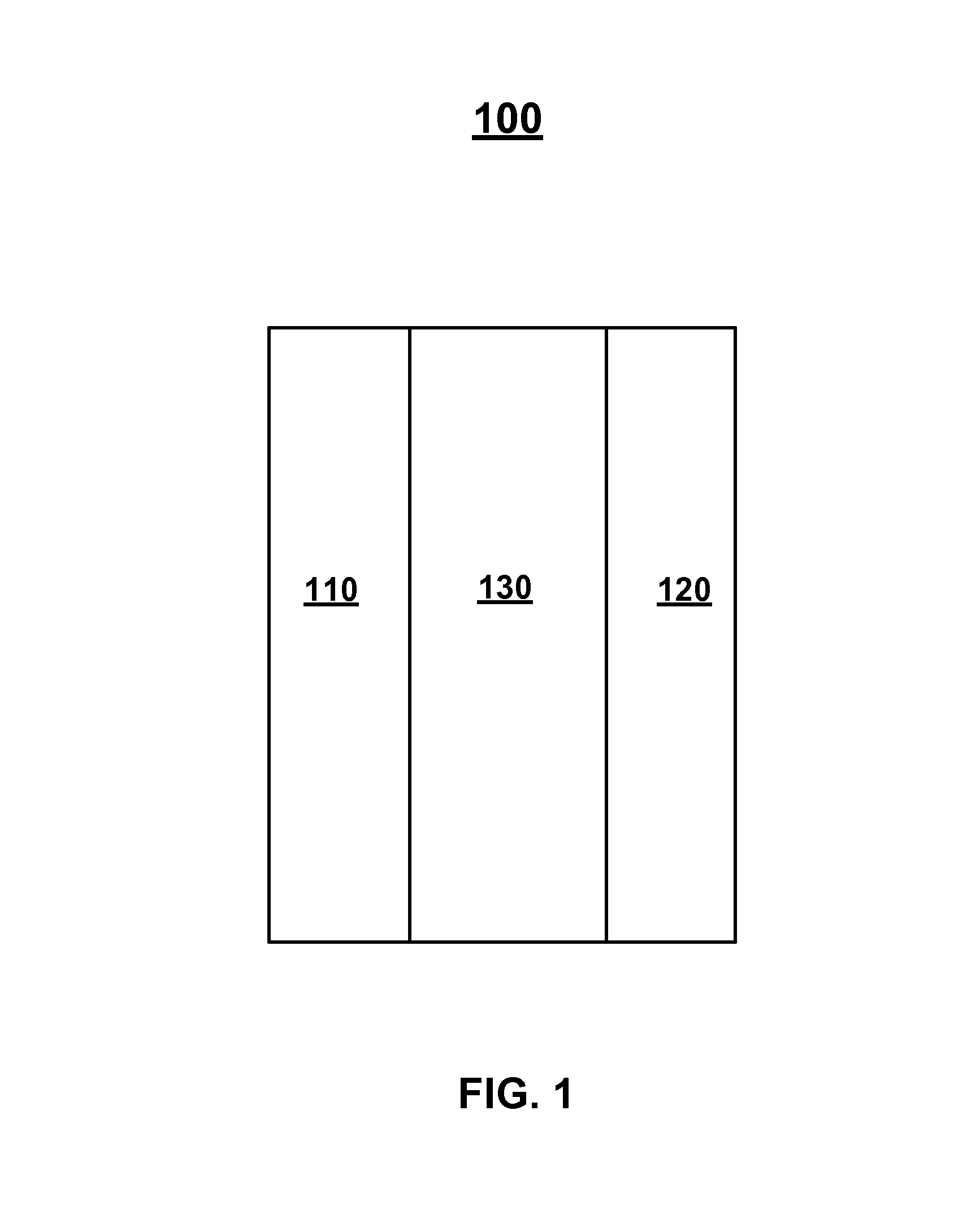
The present invention relates to a fuel cell membrane-electrode-assembly (MEA) and a method of fabricating it. The MEA includes an anode electrode, a cathode electrode, and a membrane disposed between them. The membrane is ionically conductive and made of nanofibers. The membrane is formed by electrospinning polymer solutions containing charged and uncharged polymers. The uncharged polymer can be polyphenylsulfone or a perfluorosulfonic acid polymer. The membrane can also be formed by softening and flowing at least one of the polymer fibers. The method includes fabricating each electrode separately and placing the membrane between them to form the fuel cell MEA. The technical effects of the invention include improved fuel cell performance and durability.

Problems solved by technology

A fundamental drawback of all AEMs is the fact that hydroxide anions have a lower inherent mobility than protons which adversely affects ionic conduction in an AEM [2].
To compensate for these two problems, membrane researchers have focused their attention on the use of high ion-exchange capacity polymers, but this strategy exacerbates the problems of membrane brittleness in the dry state and poor mechanical strength when the membrane is fully hydrated [3].
The platinum (Pt) catalyst utilization efficiency in such structures is not as high as desired.
There has been little research conducted to improve electrode structures and methods of fabricating fuel cell membrane-electrode-assemblies with improved catalyst utilization.
Therefore, a heretofore unaddressed need exists in the art to address the aforementioned deficiencies and inadequacies.

Method used


Image

  • Nanofiber membrane-electrode-assembly and method of fabricating same
  • Nanofiber membrane-electrode-assembly and method of fabricating same
  • Nanofiber membrane-electrode-assembly and method of fabricating same

Examples


Embodiment Construction

[0033]The invention will now be described more fully hereinafter with reference to the accompanying drawings, in which exemplary embodiments of the invention are shown. This invention may, however, be embodied in many different forms and should not be construed as limited to the embodiments set forth herein. Rather, these embodiments are provided so that this disclosure will be thorough and complete, and will fully convey the scope of the invention to those skilled in the art. Like reference numerals refer to like elements throughout.

[0034]The terms used in this specification generally have their ordinary meanings in the art, within the context of the invention, and in the specific context where each term is used. Certain terms that are used to describe the invention are discussed below, or elsewhere in the specification, to provide additional guidance to the practitioner regarding the description of the invention. For convenience, certain terms may be highlighted, for example using...


PUM

PropertyMeasurementUnit
air flow rateaaaaaaaaaa
thickaaaaaaaaaa

Abstract

In one aspect of the present invention, a fuel cell membrane-electrode-assembly (MEA) has an anode electrode, a cathode electrode, and a membrane disposed between the anode electrode and the cathode electrode. At least one of the anode electrode, the cathode electrode and the membrane is formed of electrospun nanofibers.

Description

CROSS-REFERENCE TO RELATED PATENT APPLICATIONS[0001]This application claims the benefit, pursuant to 35 U.S.C. §119(e), of U.S. provisional patent application Ser. No. 61 / 800,884, filed Mar. 15, 2013, entitled “NANOFIBER MEMBRANE-ELECTRODE-ASSEMBLY AND METHOD OF FABRICATING SAME,” by Peter N. Pintauro, Jason Ballengee and Matthew Brodt, the above disclosure of which is incorporated herein in its entireties by reference.[0002]This application also is a continuation-in-part of U.S. patent application Ser. No. 13 / 567,857, filed Aug. 6, 2012, entitled “MEMBRANES, METHODS OF MAKING SAME, AND APPLICATIONS OF SAME,” by Peter N. Pintauro and Andrew Park, which itself claims priority to and the benefit of, pursuant to 35 U.S.C. §119(e), U.S. provisional patent application Ser. No. 61 / 515,804, filed Aug. 5, 2011, entitled “NANOFIBER / NANOCAPILLARY NETWORK PROTON EXCHANGE MEMBRANE, MAKING OF SAME, AND APPLICATIONS OF SAME,” by Peter N. Pintauro and Andrew Park, all the above disclosures of whic...

Claims


Application Information

Patent Timeline
Patent Type & Authority Applications(United States)
IPC IPC(8): H01M8/10B29C48/07B29C48/21
CPCH01M8/1004H01M4/8605H01M4/8673H01M4/8825H01M2008/1095H01G11/52B32B37/182H01M8/1007B29C48/07B29C48/0021B29C48/21B29C48/142B32B2250/03B32B2457/18Y02E60/50B29K2027/18B29K2105/0014B29L2031/3468B32B5/022B32B5/08B32B37/10B32B37/18B32B2262/0238B32B2327/18
Inventor PINTAURO, PETER N.BALLENGEE, JASONBRODT, MATTHEW
Owner VANDERBILT UNIV
Learn More