Resonant micromachined biochemical sensor

a biochemical sensor and micromachine technology, applied in the field of chemical sensors, can solve the problems of reducing the q of the support structure, reducing the q of the vapor detection level, and displacing prodigious amounts of gas by the cantilever sensor, so as to reduce the energy loss to the support structure, minimize damping losses, and maximize q

Inactive Publication Date: 2014-01-30
NORLING BRIAN L +1
View PDF4 Cites 25 Cited by
  • Summary
  • Abstract
  • Description
  • Claims
  • Application Information

AI Technical Summary

Benefits of technology

The patent describes a resonant sensor system that uses a thin layer of motional mass to minimize damping losses and maximize signal quality. The system employs two dynamic balanced motional masses that are constrained to move in opposite directions, resulting in a high sensitivity to detect target chemical compounds through coatings applied to the motional mass. The system is affordable, small, light, and requires low power, making it a cost-effective and efficient alternative to ion mobility spectrometers. The technology is also less affected by particulate contamination and non-specific binding of contaminants.

Problems solved by technology

First, the cantilever sensors displace prodigious amounts of gas relative to their size because the cantilever is thin and flat relative to the direction of motion.
Additionally, the direct impingement of the sample air flow on the sensor surface has the degrading factor of potentially collecting particulate contamination of the mass-spring-damper system.
Particulate contamination commonly imparts a frequency shift error well in excess of the vapor detection level.
This approach suffers from inaccuracies due to changes in Q or pressure.

Method used


Image

  • Resonant micromachined biochemical sensor
  • Resonant micromachined biochemical sensor
  • Resonant micromachined biochemical sensor

Examples


Embodiment Construction

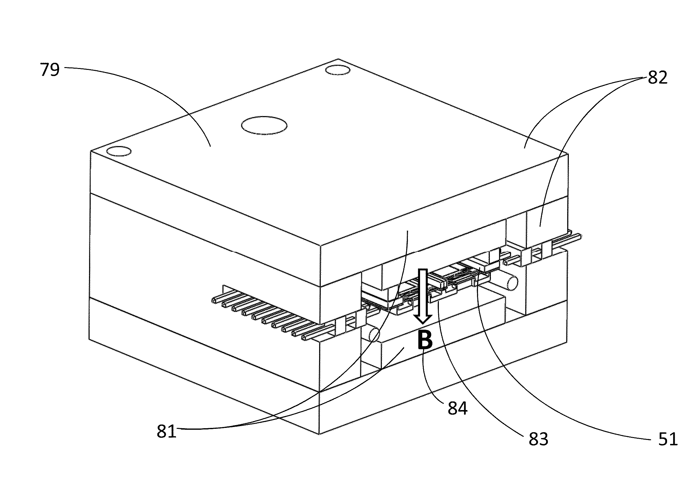
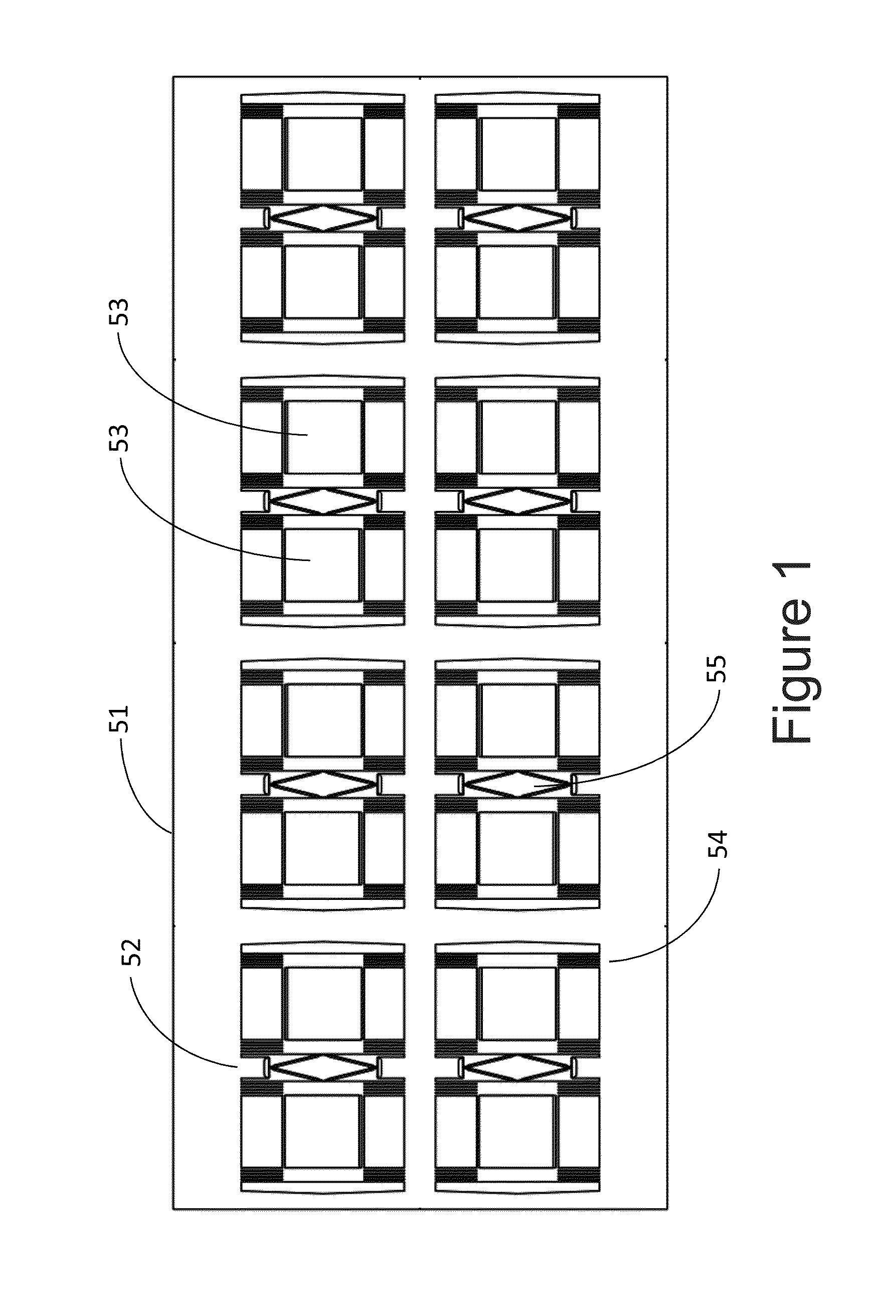
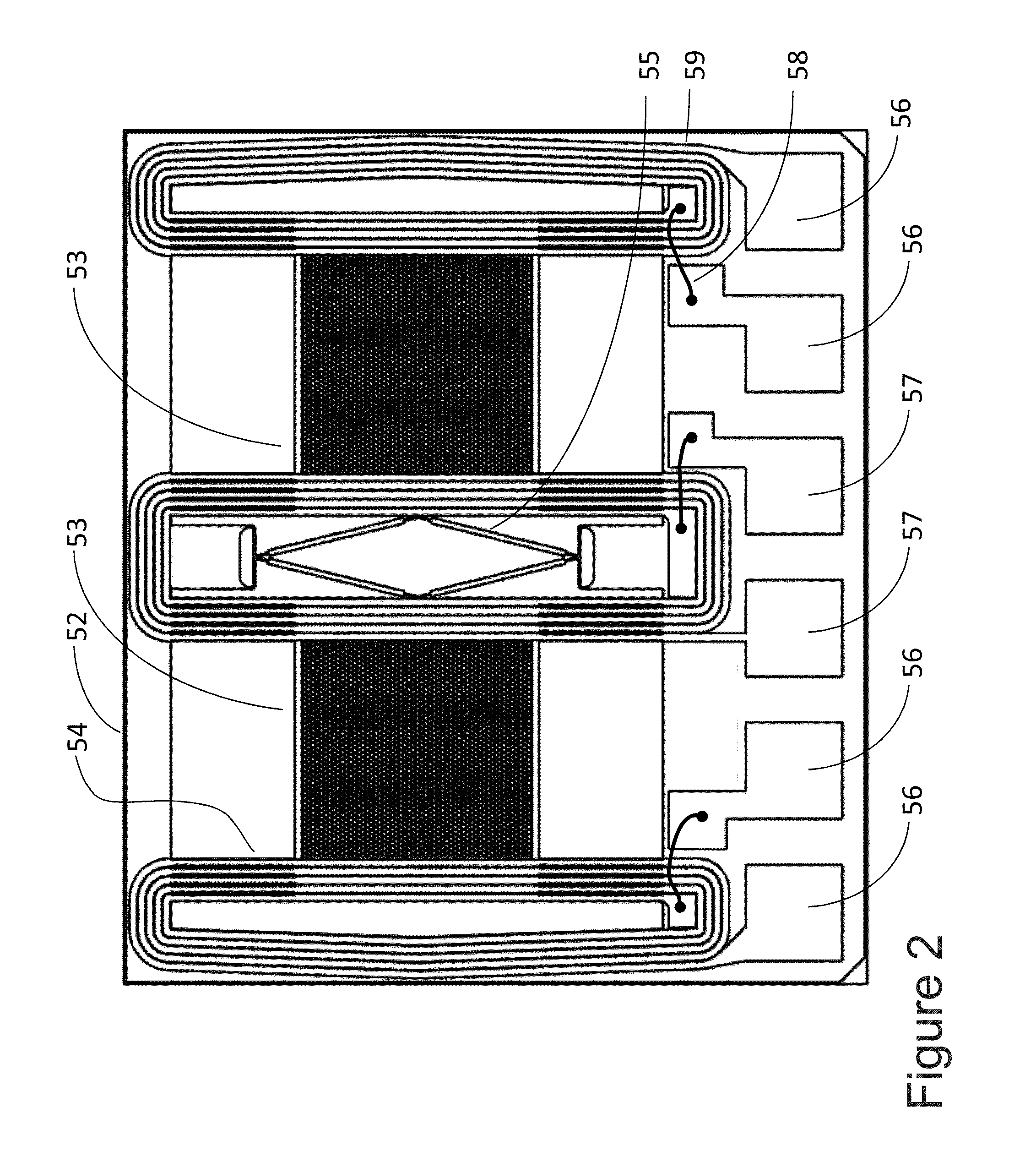
[0063]The present application is a sensing system for detection of chemicals, biological compounds, and other potential items which impart a change of mass. At the heart of the system is a spring-mass-damper mechanical system that is maintained at resonance by electronics at its damped natural frequency. When the mass of the spring-mass system changes, the frequency of the system changes. This change in frequency is the essential signal for biochemical detection. The advantage of measuring frequency change is the ability to achieve accuracy of measurement orders of magnitude better than analog-to-digital convertor technology. Additionally, the signal processing is virtually all-digital with the inherent stability of digital signal processing.

[0064]The chemical sample collection / concentration system also has the advantage of capturing both particulate and vapor target chemicals. This is a significant advantage because some chemicals, such as explosives, have low vapor pressures and a...


PUM

PropertyMeasurementUnit
massaaaaaaaaaa
weight ratioaaaaaaaaaa

Abstract

A sensor system is formed from a micro machined resonant structure with multiple resonant elements, a tracking resonator control electronics, and signal processing algorithms. The moving elements of the resonator are coated with chemically active materials that change mass when exposed to the target chemical resulting in a change in frequency or period of oscillation. The changes in frequency or period are processed by multi-sensor chemical detection algorithms to identify chemical types and concentrations. In essence, the resonator and drive electronics form a closed loop oscillator operating at the resonator's natural frequency. The resonators are formed from silicon using photolithographic processes. The resonator design includes in-plane resonant motion combined with dynamic balance to operate with a high Q even in the presence of atmospheric pressure.

Description

CROSS-REFERENCE TO RELATED APPLICATIONS[0001]This application is a continuation-in-part of co-pending U.S. application Ser. No. 13 / 344,614, filed Jan. 5, 2012, which claims priority to U.S. Provisional Patent Application Ser. No. 61 / 460,694, filed on Jan. 5, 2011, the disclosure of which is incorporated by reference herein in its entirety.FIELD OF THE INVENTION[0002]The present invention relates to chemical sensors, including biosensors, used in trace chemical detection, explosives detection, chemical hazard detection and biological hazard detection.BACKGROUND OF THE INVENTION[0003]Sensors for detecting explosives typically employ cantilever resonators driven by electrostatic forces or electromagnetic forces and capacitive pickoff. These sensors typically operate by flowing the sample volumes of air over the sensors directly over the resonant cantilever. These motional displacements of the cantilever sensor designs have several shortcomings. First, the cantilever sensors displace pr...

Claims


Application Information

Patent Timeline
Patent Type & Authority Applications(United States)
IPC IPC(8): G01N5/02
CPCG01N1/405G01N5/02G01R33/1261G01N2001/2223G01R33/0286
Inventor NORLING, BRIAN L.DUNFIELD, JOHN C.G.
Owner NORLING BRIAN L
Why Eureka
Try Eureka