Disengageable coolant pump for engine

a technology of coolant pump and engine, which is applied in the direction of machines/engines, positive displacement liquid engines, mechanical equipment, etc., can solve the problems that the cooling proportion of the engine speed may not be desirable, and achieve the effects of reducing friction, reducing friction, and speeding up the cooling of the intake air charg

Active Publication Date: 2014-01-16
FORD GLOBAL TECH LLC
View PDF6 Cites 6 Cited by
  • Summary
  • Abstract
  • Description
  • Claims
  • Application Information

AI Technical Summary

Benefits of technology

[0003]A motor-vehicle engine system will typically include an engine-driven coolant pump (known also as a ‘water pump’). The coolant pump circulates liquid coolant through jackets that surround the cylinder head or block of the engine to provide continuous cooling during engine operation. Recent coolant-pump configurations recognize the advantage of allowing the pumping rate—thus, the rate at which heat is carried away by the coolant—to vary with changing engine conditions. Specifically, after the engine has warmed to its normal operating temperature, it is desirable to operate the coolant pump in proportion to engine speed so that overheating is avoided and the normal operating temperature is maintained. When the engine is quite cool, however—e.g., following a cold start—cooling in proportion to engine speed may not be desirable. Instead, it may be desirable to allow the engine to warm to its normal operating temperature as quickly as possible. This strategy provides fuel-economy benefits deriving from faster viscosity reduction of the engine lubricant, which lowers friction, and faster warming of the intake air charge, which reduces pumping losses and increases EGR tolerance. Prompt engine warm-up also promotes faster catalyst light-off in the exhaust system, for improved emissions-control performance.

Problems solved by technology

When the engine is quite cool, however—e.g., following a cold start—cooling in proportion to engine speed may not be desirable.

Method used


Image

  • Disengageable coolant pump for engine
  • Disengageable coolant pump for engine
  • Disengageable coolant pump for engine

Examples


Embodiment Construction

[0011]Aspects of this disclosure will now be described by example and with reference to the illustrated embodiments listed above. Components, process steps, and other elements that may be substantially the same in one or more embodiments are identified coordinately and are described with minimal repetition. It will be noted, however, that elements identified coordinately may also differ to some degree. It will be further noted that the drawing figures included in this disclosure are schematic and generally not drawn to scale. Rather, the various drawing scales, aspect ratios, and numbers of components shown in the figures may be purposely distorted to make certain features or relationships easier to see.

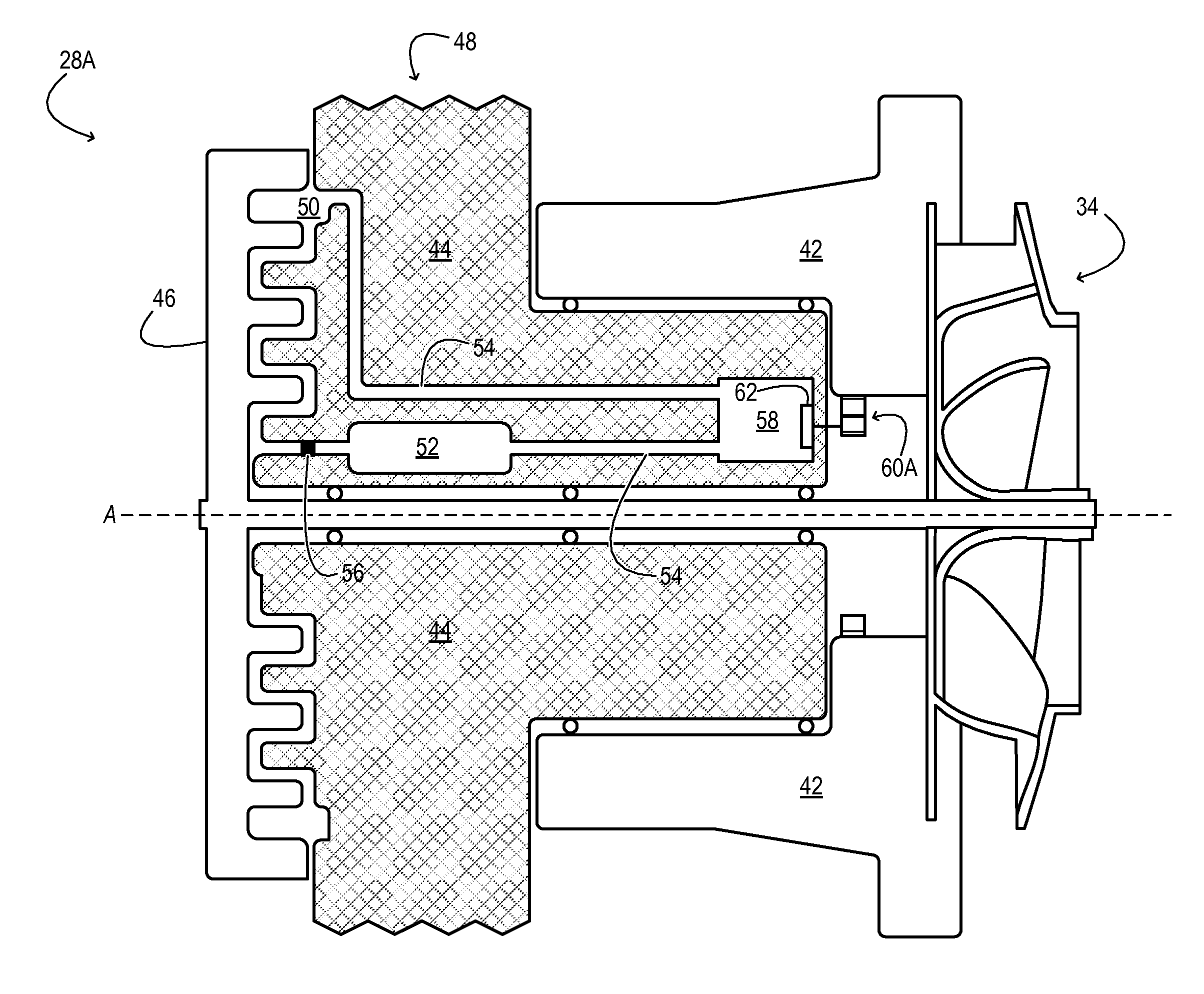
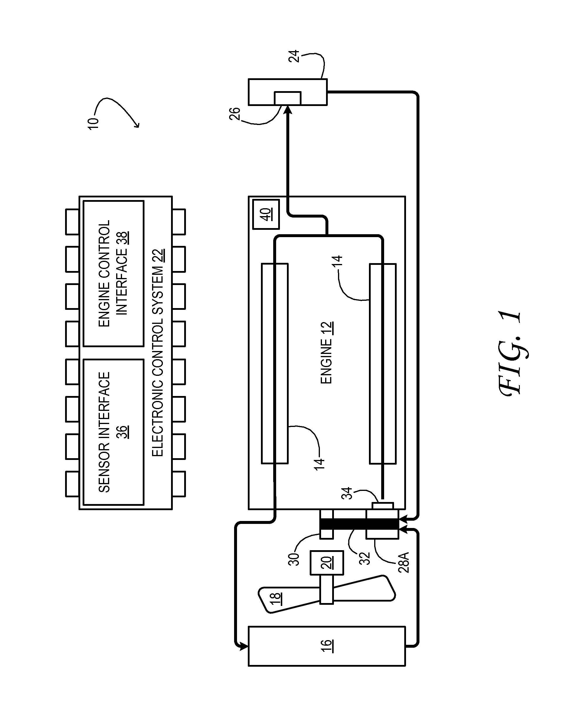
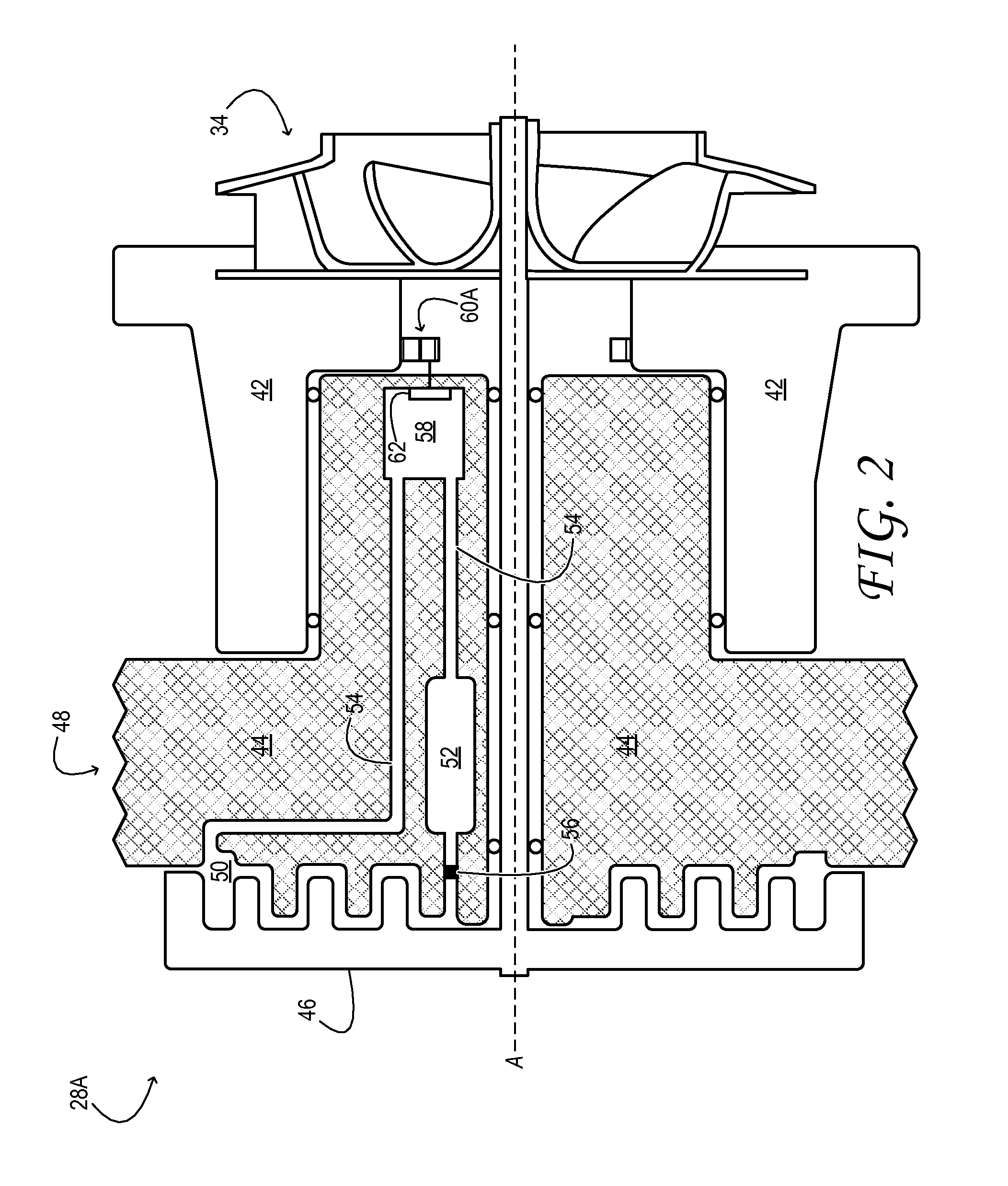
[0012]FIG. 1 shows aspects of an example engine system 10 in one embodiment. The engine system includes an engine 12, which inducts air, consumes fuel, and releases heat, exhaust, and mechanical energy. The engine may, for example, be a gasoline or diesel engine of a motor vehicle. E...


PUM


Abstract

A coolant pump includes a drive wheel, a driven wheel, and a coupling-control pump. The driven wheel is connected to a coolant impeller and coupled by a variable degree to the drive wheel, the degree of coupling responsive to an amount of fluid confined between the drive wheel and the driven wheel. The coupling-control pump is configured to change the amount of fluid confined between the drive wheel and the driven wheel based on a variable control signal.

Description

CROSS REFERENCE TO RELATED APPLICATIONS[0001]This patent application claims priority to German Patent Application DE 102012212325.3, filed Jul. 13, 2012, the entire contents of which are incorporated by reference herein, for all purposes.TECHNICAL FIELD[0002]This patent application relates to the field of motor-vehicle engineering, and more particularly, to a coolant pump for a motor-vehicle engine system.BACKGROUND AND SUMMARY[0003]A motor-vehicle engine system will typically include an engine-driven coolant pump (known also as a ‘water pump’). The coolant pump circulates liquid coolant through jackets that surround the cylinder head or block of the engine to provide continuous cooling during engine operation. Recent coolant-pump configurations recognize the advantage of allowing the pumping rate—thus, the rate at which heat is carried away by the coolant—to vary with changing engine conditions. Specifically, after the engine has warmed to its normal operating temperature, it is de...

Claims


Application Information

Patent Timeline
Patent Type & Authority Applications(United States)
IPC IPC(8): F04B17/05
CPCF04B17/05F04D13/022F04D15/0066F01P7/14
Inventor TOBERGTE, MICHAELPINGEN, BERTSCHUMACHER, BERNDMEHRING, JANHOHENBOEKEN, KAY
Owner FORD GLOBAL TECH LLC
Why Eureka
Try Eureka