Mechanical pencil

a technology of mechanical pencils and pencils, applied in the field of mechanical pencils, can solve the problems of local abrade (partially wear), considerable reduction in writing efficiency, and bold drawing lines, and achieve the effects of preventing local abrasion of writing leads, easy rotational operation, and improved writing efficiency

Active Publication Date: 2014-01-16
MITSUBISHI PENCIL CO LTD
View PDF2 Cites 5 Cited by
  • Summary
  • Abstract
  • Description
  • Claims
  • Application Information

AI Technical Summary

Benefits of technology

[0019]According to the above-described mechanical pencil in accordance with the present invention, on application of the writing pressure, the rotor which constitutes the rotational drive mechanism is rotationally driven in one direction, which is transmitted to the writing lead so that the writing lead is rotationally driven in the same direction. Thus, it is possible to prevent local abrasion of the writing lead according to the progress of the writing and to solve the problem that the thickness of a drawn line and the boldness of the drawn line may change badly.
[0020]Further, since it is arranged that the component arranged to extend from the body cylinder forwardly or rearwardly of the body cylinder (for example, the slider which supports the pipe end or the knock cover which projects rearwardly of the body cylinder) is rotationally driven in conjunction with the rotational motion of the above-mentioned rotor, it is possible to check the rotation state easily.
[0021]In addition, since the display means is provided for the above-mentioned component, i.e., the slider or the knock cover, the rotational operation can be checked more clearly.
[0022]According to these arrangements, as the writing proceeds, the slider which supports the pipe end or the knock cover which projects rearwardly of the body cylinder is rotationally driven in a stepwise manner, thereby causing a user to have interests or a pleasure somewhat and also appealing considerable product differentiation. Further, when inspecting and confirming operation of the mechanical pencil at the time of manufacture and assembly, it is possible to easily visually determine whether it is of a good quality or not.BRIEF EXPLANATION OF THE DRAWINGS
[0023]FIG. 1 is a perspective view of a first half part (partially broken-away) of a mechanical pencil in accordance with the present invention.
[0024]FIG. 2 is a fragmentary sectional side elevation similarly showing the first half part.

Problems solved by technology

In the case where the body cylinder is thus inclined for writing, there arises a phenomenon that a drawn line becomes bold as compared with that in the beginning, since the writing lead may locally abrade (partially wear) as the writing proceeds.
However, when you write down with the body cylinder being rotated, there arises a problem in that operation of re-holding the body cylinder is required while the writing proceeds, leading to considerable reduction in writing efficiency.
However, in the case of the mechanical pencil whose exterior may not be cylindrical and which may be designed to have a projection in the middle or which is a side-knock-type mechanical pencil, it is difficult to write by re-holding the body cylinder to be rotated in a stepwise manner as described above.
However, according to the above-mentioned mechanical when the rotor is rotated, there is a problem in that the writing lead needs to have a large enough retreat stroke to allow the projection on the rotor side to pass over the vertical projection formed in the body cylinder.
Thus, it is necessary to carry out the particular operation of rotating the writing lead when writing, and it is difficult to improve writing efficiency.

Method used


Image

  • Mechanical pencil
  • Mechanical pencil
  • Mechanical pencil

Examples


Embodiment Construction

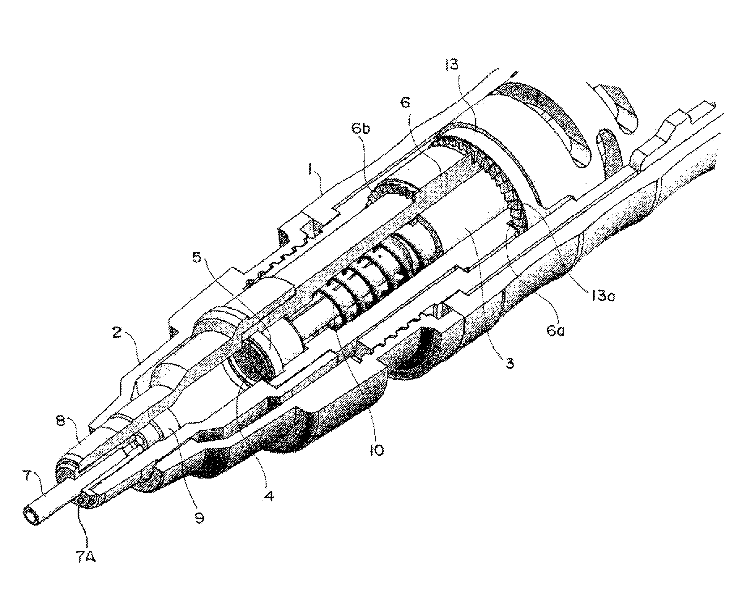
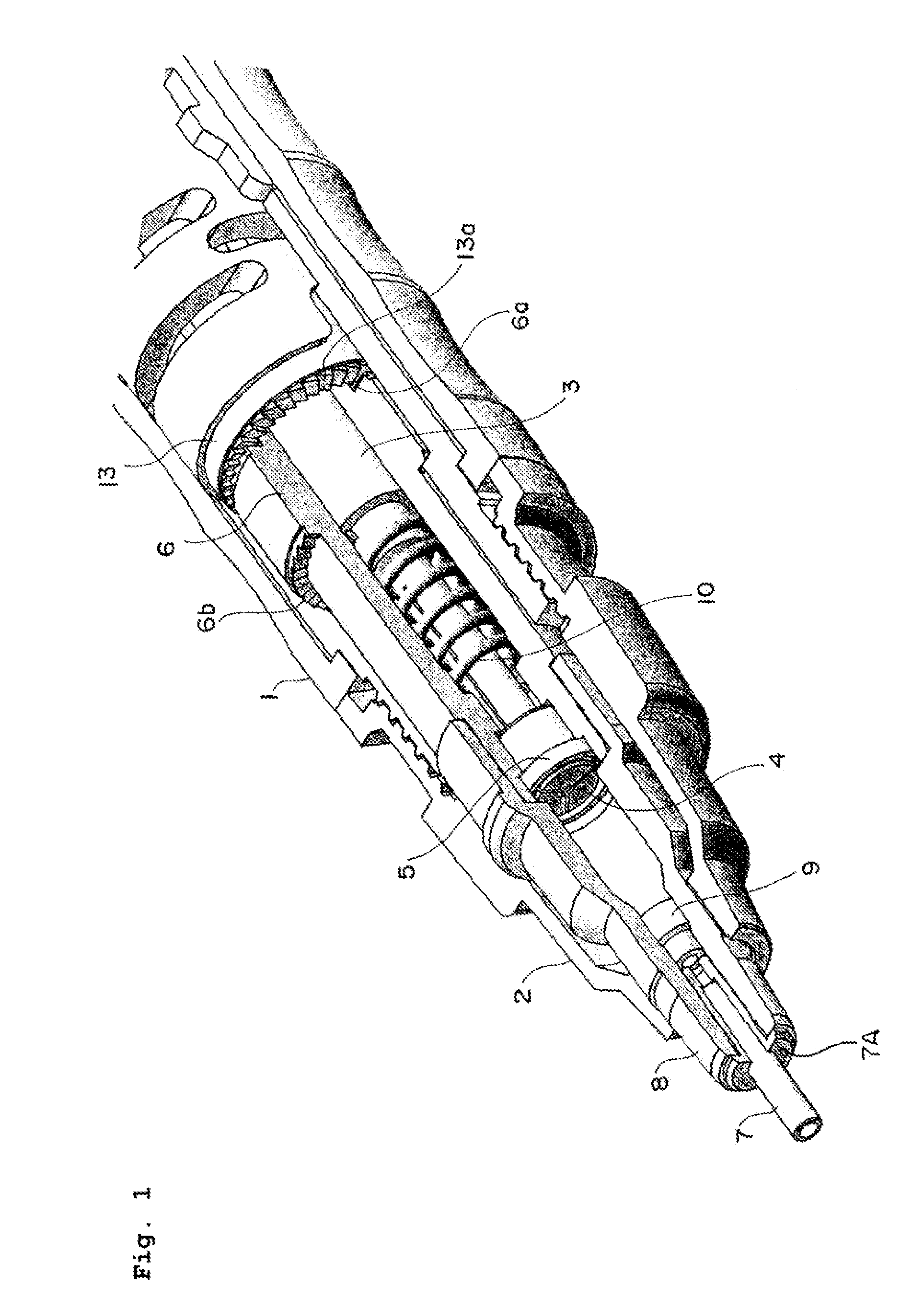
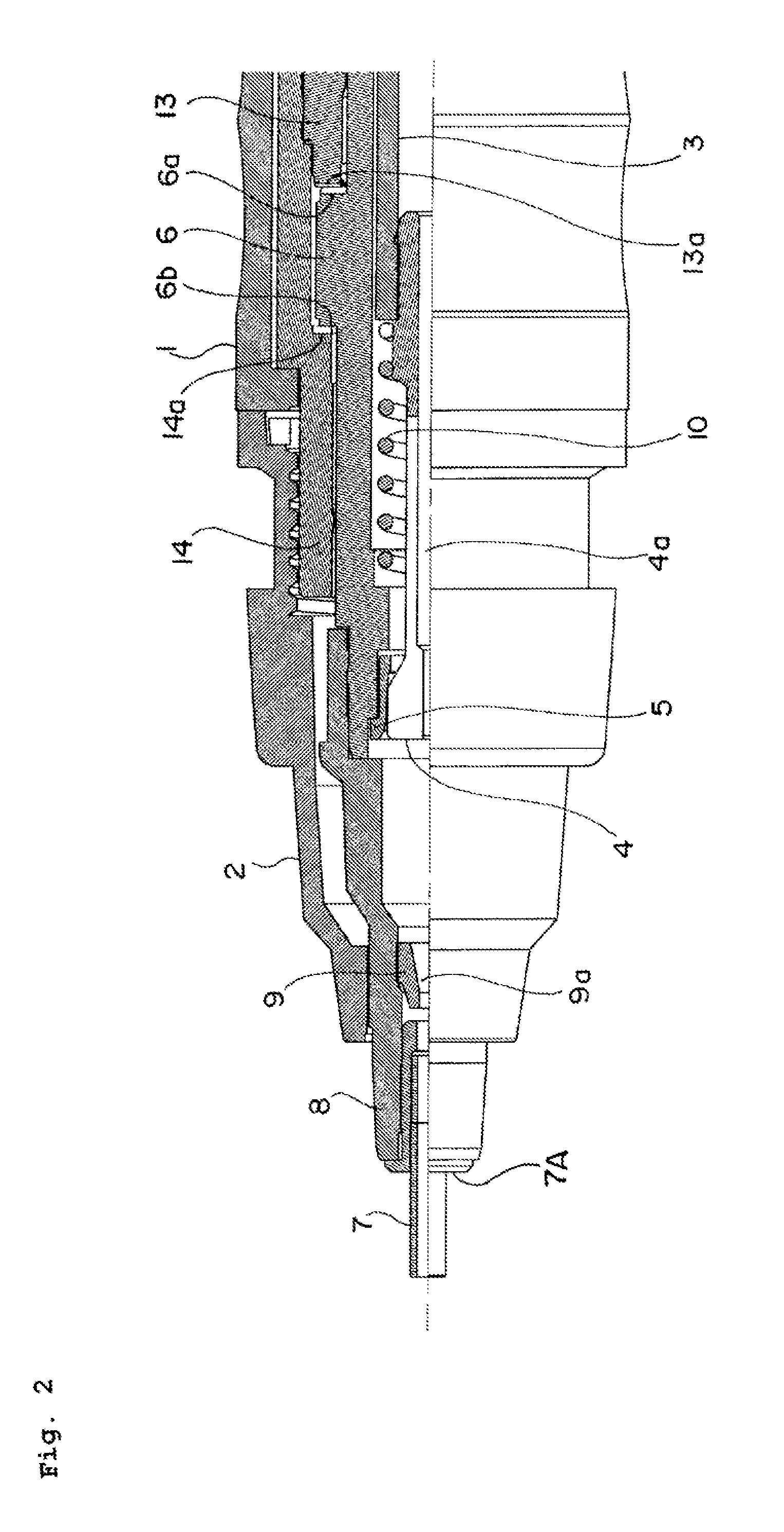
[0033]Hereinafter, a mechanical pencil in accordance with the present invention will be described with reference to the embodiments illustrated in the drawings. FIGS. 1 and 2 show a first half part of the mechanical pencil which is a principal part of the present invention. FIG. 1 is a perspective view showing its principal part, partially broken-away, and FIG. 2 is a side elevation where a left half portion is shown in section.

[0034]Reference numeral 1 denotes a body cylinder which constitutes the exterior, and reference numeral 2 indicates a base attached to a tip portion of the above-mentioned body cylinder 1. A cylindrical lead case 3 is accommodated coaxially in the center of the above-mentioned body cylinder 1, and a chuck 4 is connected with a tip portion of the lead case 3.

[0035]The chuck 4 is mounted so that a through hole 4a is formed along an axis thereof, a tip portion is divided in three directions, and the divided tip portions are loosely fitted in a clamp 5 which is f...


PUM


Abstract

A mechanical pencil having a rotational drive mechanism which gradually rotates a writing lead on application of writing pressure and allowing rotational operation of the writing lead to be known reliably. First and second cam faces 6a and 6b are respectively formed at one end face and the other end face of a rotor 6 in an axial direction, and first and second fixed cam faces 13a and 14a arranged on the body cylinder side so as to respectively face the first and the second cam faces are provided to form the rotational drive mechanism for the writing lead. A plurality of grooves 8a in the axial direction are formed at a slider 8 of a pipe end 7 which projects forwardly from a body cylinder 1. Therefore, the user can see the grooves 8a (provided for the slider 8) rotated by rotation. of the rotor 6.

Description

TECHNICAL FIELD[0001]The present invention relates to a mechanical pencil which can rotate a writing lead (refill lead) by writing pressure.BACKGROUND ART[0002]In the case of writing with a mechanical pencil, it is generally often the case that the mechanical pencil is not used in a situation where a body cylinder is perpendicular to a writing side (page), but used in a situation where the body cylinder is somewhat inclined to the writing side. In the case where the body cylinder is thus inclined for writing, there arises a phenomenon that a drawn line becomes bold as compared with that in the beginning, since the writing lead may locally abrade (partially wear) as the writing proceeds. Further, not only the drawn line changes in boldness, but also there arises a phenomenon that the drawn line changes in thickness (drawn line becomes thin) as the writing proceeds, since a contact area of the writing lead changes with respect to the writing side.[0003]In order to avoid the above-ment...

Claims


Application Information

Patent Timeline
Patent Type & Authority Applications(United States)
IPC IPC(8): B43K21/08
CPCB43K21/08B43K21/00B43K21/003B43K21/006B43K21/027B43K21/16B43K21/22B43K29/02B43K29/08
Inventor IZAWA, HIROTAKEKOBAYASHI, TAKESHINAKAYAMA, KYO
Owner MITSUBISHI PENCIL CO LTD
Why Eureka
Try Eureka